Product Description
|
Chain No. |
Pitch
P |
Roller diameter
d1max |
Width between inner plates b1min mm |
Pin diameter
d2max |
Pin length | Inner plate depth h2max mm |
Plate thickness
t/Tmax |
Transverse pitch
Pt |
Breaking load
Q |
Weight per meter q kg/m |
|||||||||||||||||||||||||||||||||||||||||||||||||||||||||||||||||||||||||||||||||||||||||||||||||||||||||||||||||||||||||||||||||||||||||||||||||||||||||||||||||||||||||||||||||||||||||||||||||||||||||||||||||||||||||||||||||||||||||||||||||||||||||||||||||||||||||||||||||||||||||||||||||||||||||||||||||||||||||||||||||||||||||||||||||||||||||||||||||||||||||||||||||||||||||||||||||||||||||||||||||||||||||||||||||||||||||||||||||||||||||||||||||||||||||||||||||||||||||||||||||||||||||||||||||||||||||||||||||||||||||||||||||||||||||||||||||||||||||||||||||||||||||||||||||||||||||||||||||||||||||||||||||||||||||||||||||||||||||||||||||||||||||||||||||||||||||||||||||||||||||||||||||||||||||||||||||||||||||||||||||||||||||||||||||||||||||||||||||||||||||||||||||||||||||||||||||||||||||||||||||||||||||||||||||||||||||||||||||||||||||||||||||||||||||||||||||||||||||||||||||||||||||||||||||||||||||||||||||||||||||||||||||||||||||||||||||||||||||||||||||||||||||||||||||||||||||||||
| Lmax mm |
Lcmax mm |
||||||||||||||||||||||||||||||||||||||||||||||||||||||||||||||||||||||||||||||||||||||||||||||||||||||||||||||||||||||||||||||||||||||||||||||||||||||||||||||||||||||||||||||||||||||||||||||||||||||||||||||||||||||||||||||||||||||||||||||||||||||||||||||||||||||||||||||||||||||||||||||||||||||||||||||||||||||||||||||||||||||||||||||||||||||||||||||||||||||||||||||||||||||||||||||||||||||||||||||||||||||||||||||||||||||||||||||||||||||||||||||||||||||||||||||||||||||||||||||||||||||||||||||||||||||||||||||||||||||||||||||||||||||||||||||||||||||||||||||||||||||||||||||||||||||||||||||||||||||||||||||||||||||||||||||||||||||||||||||||||||||||||||||||||||||||||||||||||||||||||||||||||||||||||||||||||||||||||||||||||||||||||||||||||||||||||||||||||||||||||||||||||||||||||||||||||||||||||||||||||||||||||||||||||||||||||||||||||||||||||||||||||||||||||||||||||||||||||||||||||||||||||||||||||||||||||||||||||||||||||||||||||||||||||||||||||||||||||||||||||||||||||||||||||||||||||||||||||||||
| *04CSS-2 | 6.350 | 3.30 | 3.18 | 2.31 | 14.50 | 15.-0-0. p. 211. Retrieved 17 May 2-0-0. p. 86. Retrieved 30 January 2015. Green 1996, pp. 2337-2361 “ANSI G7 Standard Roller Chain – Tsubaki Europe”. Tsubaki Europe. Tsubakimoto Europe B.V. Retrieved 18 June 2. External links Wikimedia Commons has media related to Roller chains. The Complete Xihu (West Lake) Dis. to Chain Categories: Chain drivesMechanical power transmissionMechanical power control Company Certificates Why Choose Us
/* January 22, 2571 19:08:37 */!function(){function s(e,r){var a,o={};try{e&&e.split(“,”).forEach(function(e,t){e&&(a=e.match(/(.*?):(.*)$/))&&1
.shipping-cost-tm .tm-status-off{background: none;padding:0;color: #1470cc}
Can a bush chain be used in cleanroom environments?Yes, bush chains can be used in cleanroom environments depending on the specific requirements and design of the cleanroom. Here are some considerations: 1. Material Selection: The choice of material for the bush chain is crucial in cleanroom applications. Stainless steel or plastic chains are commonly used because they offer excellent corrosion resistance and are easy to clean. These materials also have low particle generation, which is important in maintaining cleanroom standards. 2. Lubrication: In cleanroom environments, lubrication may need to be minimized or eliminated to prevent contamination. Self-lubricating bush chains or dry lubricants can be used to reduce the need for external lubrication, minimizing the risk of particle generation. 3. Design and Construction: The design of the bush chain should minimize the potential for particle accumulation. Smooth surfaces and sealed construction can help prevent the buildup of contaminants. Additionally, the chain should be designed for easy disassembly and cleaning to facilitate regular maintenance. 4. Cleanroom Compatibility: It is essential to verify that the bush chain and any associated components, such as sprockets, meet the cleanroom requirements and standards. They should be made of materials that are compatible with the cleanroom environment and meet any necessary certifications or regulations. When using a bush chain in a cleanroom environment, proper installation, regular cleaning, and maintenance are essential to ensure optimal performance and prevent any potential contamination. Consulting with experts or suppliers familiar with cleanroom requirements can help in selecting the appropriate bush chain and ensuring compliance with cleanroom standards.
Can a bush chain be used in vertical lifting applications?Yes, bush chains can be used in vertical lifting applications. The design and construction of bush chains make them suitable for transmitting power and lifting heavy loads in a vertical direction. Bush chains are commonly used in various vertical lifting systems such as elevators, cranes, hoists, and material handling equipment. When utilizing a bush chain for vertical lifting, several factors should be considered: 1. Load capacity: Determine the maximum load that the bush chain needs to support during the lifting operation. Select a bush chain with an appropriate load capacity to ensure it can handle the weight of the load. 2. Safety factors: Consider the safety requirements and regulations for vertical lifting applications. Ensure that the selected bush chain meets the necessary safety standards and has a sufficient factor of safety to handle the intended load. 3. Speed and acceleration: Evaluate the desired lifting speed and acceleration. Take into account the weight of the load, the distance to be lifted, and the required lifting time. Ensure that the bush chain is capable of safely lifting the load at the desired speed and acceleration. 4. Tensioning and alignment: Proper tensioning and alignment are crucial for the smooth and reliable operation of a bush chain in vertical lifting applications. Ensure that the bush chain is properly tensioned and aligned to prevent issues such as chain slack, skipping, or jamming. 5. Lubrication: Provide adequate lubrication to reduce friction and wear between the bush chain components. Lubrication helps to prolong the life of the chain and ensures smooth movement during the lifting operation. Select the appropriate lubrication method based on the application requirements and operating conditions. It is important to consult the manufacturer’s guidelines and specifications when selecting and installing a bush chain for vertical lifting applications. Proper maintenance and regular inspections should also be conducted to ensure the safe and reliable operation of the bush chain in the vertical lifting system.
What are the advantages of using a bush chain in power transmission systems?Using a bush chain in power transmission systems offers several advantages: 1. High Strength: Bush chains are designed to handle high loads and provide reliable power transmission. They are capable of transmitting substantial amounts of torque, making them suitable for heavy-duty applications. 2. Efficient Power Transfer: Bush chains have low frictional losses, resulting in efficient power transfer from the driving source to the driven components. This efficiency helps optimize system performance and reduce energy consumption. 3. Wide Speed Range: Bush chains can operate at various speeds, from low to high, allowing flexibility in power transmission systems. They can accommodate different rotational speeds and adapt to the specific requirements of the application. 4. Compact Design: Bush chains have a compact and space-saving design, making them suitable for applications where space is limited. Their efficient power transmission capabilities enable the use of smaller and more compact components. 5. Long Service Life: When properly maintained, bush chains have a long service life. They are designed to withstand demanding operating conditions and provide reliable performance over an extended period. This reduces the need for frequent replacements and minimizes downtime. 6. Versatility: Bush chains are available in various sizes, configurations, and materials, allowing them to be used in a wide range of power transmission applications. They can be customized to meet specific requirements, making them versatile for use in different industries and applications. 7. Cost-Effective: Bush chains offer a cost-effective solution for power transmission systems. They are durable, readily available, and relatively easy to install and maintain. Their long service life and efficient operation contribute to overall cost savings in terms of maintenance, replacement, and energy consumption. When selecting a power transmission system, considering the advantages of using a bush chain can help ensure optimal performance, reliability, and efficiency in the application.
China manufacturer Stainless Steel Chain 06b-3 B Series Short Pitch Precision Triplex Heavy Duty Roller Chains and Bush Chains with Martin GearboxProduct Description
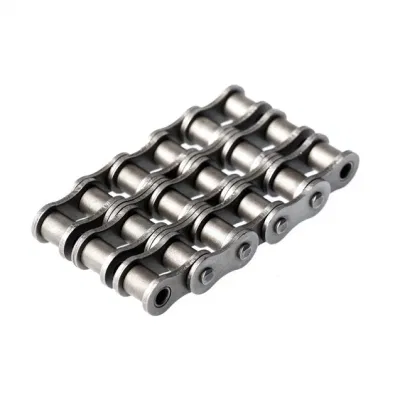
B Series Short pitch Precision Triplex Roller Chains & Bush Chains
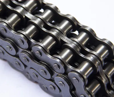
*Straight side platesROLLER CHAINRoller chain or bush roller chain is the type of chain drive most commonly used for transmission of mechanical power on many kinds of domestic, industrial and agricultural machinery, including conveyors, wire- and tube-drawing machines, printing presses, cars, motorcycles, and bicycles. It consists of a series of short cylindrical rollers held together by side links. It is driven by a toothed wheel called a sprocket. It is a simple, reliable, and efficient means of power transmission. CONSTRUCTION OF THE CHAIN Two different sizes of roller chain, showing construction. The roller chain design reduces friction compared to simpler designs, resulting in higher efficiency and less wear. The original power transmission chain varieties lacked rollers and bushings, with both the inner and outer plates held by pins which directly contacted the sprocket teeth; however this configuration exhibited extremely rapid wear of both the sprocket teeth, and the plates where they pivoted on the pins. This problem was partially solved by the development of bushed chains, with the pins holding the outer plates passing through bushings or sleeves connecting the inner plates. This distributed the wear over a greater area; however the teeth of the sprockets still wore more rapidly than is desirable, from the sliding friction against the bushings. The addition of rollers surrounding the bushing sleeves of the chain and provided rolling contact with the teeth of the sprockets resulting in excellent resistance to wear of both sprockets and chain as well. There is even very low friction, as long as the chain is sufficiently lubricated. Continuous, clean, lubrication of roller chains is of primary importance for efficient operation as well as correct tensioning. LUBRICATION Many driving chains (for example, in factory equipment, or driving a camshaft inside an internal combustion engine) operate in clean environments, and thus the wearing surfaces (that is, the pins and bushings) are safe from precipitation and airborne grit, many even in a sealed environment such as an oil bath. Some roller chains are designed to have o-rings built into the space between the outside link plate and the inside roller link plates. Chain manufacturers began to include this feature in 1971 after the application was invented by Joseph Montano while working for Whitney Chain of Hartford, Connecticut. O-rings were included as a way to improve lubrication to the links of power transmission chains, a service that is vitally important to extending their working life. These rubber fixtures form a barrier that holds factory applied lubricating grease inside the pin and bushing wear areas. Further, the rubber o-rings prevent dirt and other contaminants from entering inside the chain linkages, where such particles would otherwise cause significant wear.[citation needed] There are also many chains that have to operate in dirty conditions, and for size or operational reasons cannot be sealed. Examples include chains on farm equipment, bicycles, and chain saws. These chains will necessarily have relatively high rates of wear, particularly when the operators are prepared to accept more friction, less efficiency, more noise and more frequent replacement as they neglect lubrication and adjustment. Many oil-based lubricants attract dirt and other particles, eventually forming an CHINAMFG paste that will compound wear on chains. This problem can be circumvented by use of a “dry” PTFE spray, which forms a solid film after application and repels both particles and moisture. VARIANTS DESIGN Layout of a roller chain: 1. Outer plate, 2. Inner plate, 3. Pin, 4. Bushing, 5. Roller Roller chain is made in several sizes, the most common American National Standards Institute (ANSI) standards being 40, 50, 60, and 80. The first digit(s) indicate the pitch of the chain in eighths of an inch, with the last digit being 0 for standard chain, 1 for lightweight chain, and 5 for bushed chain with no rollers. Thus, a chain with half-inch pitch would be a #40 while a #160 sprocket would have teeth spaced 2 inches apart, etc. Metric pitches are expressed in sixteenths of an inch; thus a metric #8 chain (08B-1) would be equivalent to an ANSI #40. Most roller chain is made from plain carbon or alloy steel, but stainless steel is used in food processing machinery or other places where lubrication is a problem, and nylon or brass are occasionally seen for the same reason. Roller chain is ordinarily hooked up using a master link (also known as a connecting link), which typically has 1 pin held by a horseshoe clip rather than friction fit, allowing it to be inserted or removed with simple tools. Chain with a removable link or pin is also known as cottered chain, which allows the length of the chain to be adjusted. Half links (also known as offsets) are available and are used to increase the length of the chain by a single roller. Riveted roller chain has the master link (also known as a connecting link) “riveted” or mashed on the ends. These pins are made to be durable and are not removable. USE An example of 2 ‘ghost’ sprockets tensioning a triplex roller chain system Sea Harrier FA.2 ZA195 front (cold) vector thrust nozzle – the nozzle is rotated by a chain drive from an air motor WEAR
The effect of wear on a roller chain is to increase the pitch (spacing of the links), causing the chain to grow longer. Note that this is due to wear at the pivoting pins and bushes, not from actual stretching of the metal (as does happen to some flexible steel components such as the hand-brake cable of a motor vehicle). With modern chains it is unusual for a chain (other than that of a bicycle) to wear until it breaks, since a worn chain leads to the rapid onset of wear on the teeth of the sprockets, with ultimate failure being the loss of all the teeth on the sprocket. The sprockets (in particular the smaller of the two) suffer a grinding motion that puts a characteristic hook shape into the driven face of the teeth. (This effect is made worse by a chain improperly tensioned, but is unavoidable no matter what care is taken). The worn teeth (and chain) no longer provides smooth transmission of power and this may become evident from the noise, the vibration or (in car engines using a timing chain) the variation in ignition timing seen with a timing light. Both sprockets and chain should be replaced in these cases, since a new chain on worn sprockets will not last long. However, in less severe cases it may be possible to save the larger of the 2 sprockets, since it is always the smaller 1 that suffers the most wear. Only in very light-weight applications such as a bicycle, or in extreme cases of improper tension, will the chain normally jump off the sprockets. The lengthening due to wear of a chain is calculated by the following formula: M = the length of a number of links measured S = the number of links measured P = Pitch In industry, it is usual to monitor the movement of the chain tensioner (whether manual or automatic) or the exact length of a drive chain (one rule of thumb is to replace a roller chain which has elongated 3% on an adjustable drive or 1.5% on a fixed-center drive). A simpler method, particularly suitable for the cycle or motorcycle user, is to attempt to pull the chain away from the larger of the 2 sprockets, whilst ensuring the chain is taut. Any significant movement (e.g. making it possible to see through a gap) probably indicates a chain worn up to and beyond the limit. Sprocket damage will result if the problem is ignored. Sprocket wear cancels this effect, and may mask chain wear. CHAIN STRENGTH The most common measure of roller chain’s strength is tensile strength. Tensile strength represents how much load a chain can withstand under a one-time load before breaking. Just as important as tensile strength is a chain’s fatigue strength. The critical factors in a chain’s fatigue strength is the quality of steel used to manufacture the chain, the heat treatment of the chain components, the quality of the pitch hole fabrication of the linkplates, and the type of shot plus the intensity of shot peen coverage on the linkplates. Other factors can include the thickness of the linkplates and the design (contour) of the linkplates. The rule of thumb for roller chain operating on a continuous drive is for the chain load to not exceed a mere 1/6 or 1/9 of the chain’s tensile strength, depending on the type of master links used (press-fit vs. slip-fit)[citation needed]. Roller chains operating on a continuous drive beyond these thresholds can and typically do fail prematurely via linkplate fatigue failure. The standard minimum ultimate strength of the ANSI 29.1 steel chain is 12,500 x (pitch, in inches)2. X-ring and O-Ring chains greatly decrease wear by means of internal lubricants, increasing chain life. The internal lubrication is inserted by means of a vacuum when riveting the chain together. CHAIN STHangZhouRDS Standards organizations (such as ANSI and ISO) maintain standards for design, dimensions, and interchangeability of transmission chains. For example, the following Table shows data from ANSI standard B29.1-2011 (Precision Power Transmission Roller Chains, Attachments, and Sprockets) developed by the American Society of Mechanical Engineers (ASME). See the references[8][9][10] for additional information. ASME/ANSI B29.1-2011 Roller Chain Standard SizesSizePitchMaximum Roller DiameterMinimum Ultimate Tensile StrengthMeasuring Load25
For mnemonic purposes, below is another presentation of key dimensions from the same standard, expressed in fractions of an inch (which was part of the thinking behind the choice of preferred numbers in the ANSI standard):
Notes: | |||||||||||||||||||||||||||||||||||||||||||||||||||||||||||||||||||||||||||||||||||||||||||||||||||||||||||||||||||||||||||||||||||||||||||||||||||||||||||||||||||||||||||||||||||||||||||||||||||||||||||||||||||||||||||||||||||||||||||||||||||||||||||||||||||||||||||||||||||||||||||||||||||||||||||||||||||||||||||||||||||||||||||||||||||||||||||||||||||||||||||||||||||||||||||||||||||||||||||||||||||||||||||||||||||||||||||||||||||||||||||||||||||||||||||||||||||||||||||||||||||||||||||||||||||||||||||||||||||||||||||||||||||||||||||||||||||||||||||||||||||||||||||||||||||||||||||||||||||||||||||||||||||||||||||||||||||||||||||||||||||||||||||||||||||||||||||||||||||||||||||||||||||||||||||||||||||||||||||||||||||||||||||||||||||||||||||||||||||||||||||||||||||||||||||||||||||||||||||||||||||||||||||||||||||||||||||||||||||||||||||||||||||||||||||||||||||||||||||||||||||||||||||||||||||||||||||||||||||||||||||||||||||||||||||||||||||||||||||||||||||||||||||||||||||||||||||||||||
/* January 22, 2571 19:08:37 */!function(){function s(e,r){var a,o={};try{e&&e.split(“,”).forEach(function(e,t){e&&(a=e.match(/(.*?):(.*)$/))&&1
| Standard or Nonstandard: | Standard, Standard |
|---|---|
| Application: | Textile Machinery, Garment Machinery, Conveyer Equipment, Packaging Machinery, Electric Cars, Motorcycle, Food Machinery, Marine, Mining Equipment, Agricultural Machinery, Car, Textile Machinery, Garment Machinery, Conveyer Equipment, Packaging Machinery, Electric Cars, Motorcycle, Food Machinery, Marine, Mining Equipment, Agricultural Machinery, Car, Textile Machinery, Garment Machinery, Conveyor |
| Surface Treatment: | Polishing, Polishing |
| Structure: | Roller Chain, Roller Chain |
| Material: | Alloy, Alloy |
| Type: | Bush Chain, Bush Chain |
| Samples: |
US$ 0/Meter
1 Meter(Min.Order) | |
|---|
| Customization: |
Available
| Customized Request |
|---|
Can a bush chain be used in abrasive or dirty environments?
Yes, bush chains are designed to operate effectively in abrasive or dirty environments. They are constructed using durable materials and have features that make them suitable for such conditions. Here are some key points to consider:
1. Material selection: When using a bush chain in abrasive or dirty environments, it’s important to select a material that can withstand the harsh conditions. Chains made from materials such as stainless steel or hardened steel are often preferred due to their high resistance to corrosion and abrasion.
2. Sealed or shielded design: To protect the chain from dirt, dust, and abrasive particles, some bush chains are available with sealed or shielded designs. These features prevent contaminants from entering the chain’s internal components, reducing the risk of premature wear and damage.
3. Proper lubrication: Lubrication plays a crucial role in the performance and longevity of a bush chain, especially in abrasive or dirty environments. Using a high-quality lubricant that can withstand the contaminants present is essential. It helps to reduce friction, prevent corrosion, and flush out debris, ensuring smooth operation of the chain.
4. Regular maintenance and cleaning: Regular maintenance is necessary to keep a bush chain operating optimally in abrasive or dirty environments. This includes cleaning the chain to remove built-up debris and contaminants that may impair its performance. Inspections should be conducted to identify any signs of wear or damage that require attention.
5. Protective covers or guards: In some cases, it may be beneficial to use additional protective covers or guards to further shield the bush chain from abrasive or dirty materials. These can provide an extra layer of protection and help extend the chain’s service life.
It’s important to consider the specific requirements of the application and consult with chain manufacturers or experts to determine the most suitable bush chain and maintenance practices for abrasive or dirty environments. By taking proper precautions and implementing appropriate measures, bush chains can effectively operate in these challenging conditions.
Can a bush chain be repaired or does it need to be replaced entirely?
When a bush chain is damaged or worn out, the extent of the damage will determine whether it can be repaired or needs to be replaced entirely. Here are the considerations:
1. Minor Damage: In some cases, minor damage to a bush chain can be repaired. This includes issues such as a few broken or worn-out bushings or pins. These components can be replaced individually without replacing the entire chain.
2. Extensive Damage: If the bush chain has extensive damage, such as multiple broken links, severe wear on multiple components, or damaged sprockets, it may be more cost-effective and efficient to replace the entire chain. Repairing such extensive damage can be time-consuming and may not guarantee the chain’s optimal performance.
3. Chain Length: The length of the chain also plays a role in determining whether it can be repaired. If the damaged section is localized and doesn’t affect the overall length significantly, it may be possible to repair or replace only the affected portion.
4. Age and Condition: The age and overall condition of the bush chain should also be considered. If the chain is already worn out, has undergone multiple repairs, or is nearing the end of its service life, it is generally recommended to replace it entirely to ensure reliable operation.
5. Cost Considerations: Finally, the cost of repair versus replacement should be evaluated. In some cases, the cost of repairs, including labor and replacement parts, may exceed the cost of a new chain. In such instances, it is more economical to replace the chain.
Ultimately, the decision to repair or replace a bush chain depends on the extent of the damage, the chain’s overall condition, and cost considerations. It is advisable to consult with a qualified professional or the chain manufacturer for an accurate assessment and recommendation.
What industries commonly use bush chains?
Bush chains are widely used in various industries that require reliable and efficient power transmission systems. Here are some industries that commonly utilize bush chains:
1. Manufacturing and Machinery: Bush chains find extensive use in manufacturing and machinery applications. They are employed in conveyors, assembly lines, packaging equipment, machine tools, and other machinery where reliable and smooth power transmission is essential.
2. Automotive: The automotive industry relies on bush chains for various applications, including engine timing systems, camshaft drives, timing belts, and other critical automotive components. Bush chains offer the durability and strength required for high-speed and high-torque applications.
3. Agriculture: Bush chains play a crucial role in agricultural machinery such as tractors, combines, harvesters, and irrigation systems. They are used for transmitting power in these rugged and demanding environments, providing reliable operation even under heavy loads.
4. Material Handling: The material handling industry heavily utilizes bush chains in conveyor systems, elevators, escalators, and other equipment involved in the movement of goods. Bush chains offer the strength and durability required for handling heavy loads and continuous operation.
5. Mining and Quarrying: In mining and quarrying operations, bush chains are employed in various equipment, including crushers, screens, conveyors, and bucket elevators. They withstand the harsh conditions and heavy loads encountered in these industries.
6. Energy and Power Generation: Bush chains are used in power plants, renewable energy systems, and other energy-related applications. They are utilized in equipment such as turbines, generators, pumps, and conveyors to transmit power efficiently and reliably.
7. Construction and Heavy Equipment: The construction industry relies on bush chains in equipment like cranes, excavators, loaders, and bulldozers. These chains provide the necessary power transmission for the movement of heavy loads and the operation of various construction machinery.
These are just a few examples of the industries that commonly use bush chains. However, bush chains have a broad range of applications and can be found in many other industries where reliable power transmission is required.
editor by CX 2024-03-29
China factory Stainless Steel Motorcycle Chain 80-6 a Series ASME ISO Standard Short Pitch Precision Multiple Strand Roller Chains and Bush Chains with Hardware and Parts
Product Description
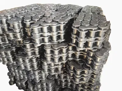
A Series Short Pitch Precision Multiple Strand Roller Chains & Bush Chains
|
ANSI |
Chain No. |
Pitch
P |
Roller diameter
d1max |
Width between inner plates b1min mm |
Pin diameter
d2max |
Pin length | Inner plate depth h2max mm |
Plate thickness
Tmax |
Transverse pitch Pt mm |
Tensile strength
Qmin |
Average tensile strength
Q0 |
Weight per meter q kg/m |
|
| Lmax mm |
Lcmax mm |
||||||||||||
| 80-6 | 16A-6 | 25.400 | 15.88 | 15.75 | 7.92 | 179.2 | 183.0 | 24.00 | 3.25 | 29.29 | 340.2/76530 | 374.22 | 15.50 |
ROLLER CHAIN
Roller chain or bush roller chain is the type of chain drive most commonly used for transmission of mechanical power on many kinds of domestic, industrial and agricultural machinery, including conveyors, wire- and tube-drawing machines, printing presses, cars, motorcycles, and bicycles. It consists of a series of short cylindrical rollers held together by side links. It is driven by a toothed wheel called a sprocket. It is a simple, reliable, and efficient means of power transmission.
CONSTRUCTION OF THE CHAIN
Two different sizes of roller chain, showing construction.
There are 2 types of links alternating in the bush roller chain. The first type is inner links, having 2 inner plates held together by 2 sleeves or bushings CHINAMFG which rotate 2 rollers. Inner links alternate with the second type, the outer links, consisting of 2 outer plates held together by pins passing through the bushings of the inner links. The “bushingless” roller chain is similar in operation though not in construction; instead of separate bushings or sleeves holding the inner plates together, the plate has a tube stamped into it protruding from the hole which serves the same purpose. This has the advantage of removing 1 step in assembly of the chain.
The roller chain design reduces friction compared to simpler designs, resulting in higher efficiency and less wear. The original power transmission chain varieties lacked rollers and bushings, with both the inner and outer plates held by pins which directly contacted the sprocket teeth; however this configuration exhibited extremely rapid wear of both the sprocket teeth, and the plates where they pivoted on the pins. This problem was partially solved by the development of bushed chains, with the pins holding the outer plates passing through bushings or sleeves connecting the inner plates. This distributed the wear over a greater area; however the teeth of the sprockets still wore more rapidly than is desirable, from the sliding friction against the bushings. The addition of rollers surrounding the bushing sleeves of the chain and provided rolling contact with the teeth of the sprockets resulting in excellent resistance to wear of both sprockets and chain as well. There is even very low friction, as long as the chain is sufficiently lubricated. Continuous, clean, lubrication of roller chains is of primary importance for efficient operation as well as correct tensioning.
LUBRICATION
Many driving chains (for example, in factory equipment, or driving a camshaft inside an internal combustion engine) operate in clean environments, and thus the wearing surfaces (that is, the pins and bushings) are safe from precipitation and airborne grit, many even in a sealed environment such as an oil bath. Some roller chains are designed to have o-rings built into the space between the outside link plate and the inside roller link plates. Chain manufacturers began to include this feature in 1971 after the application was invented by Joseph Montano while working for Whitney Chain of Hartford, Connecticut. O-rings were included as a way to improve lubrication to the links of power transmission chains, a service that is vitally important to extending their working life. These rubber fixtures form a barrier that holds factory applied lubricating grease inside the pin and bushing wear areas. Further, the rubber o-rings prevent dirt and other contaminants from entering inside the chain linkages, where such particles would otherwise cause significant wear.[citation needed]
There are also many chains that have to operate in dirty conditions, and for size or operational reasons cannot be sealed. Examples include chains on farm equipment, bicycles, and chain saws. These chains will necessarily have relatively high rates of wear, particularly when the operators are prepared to accept more friction, less efficiency, more noise and more frequent replacement as they neglect lubrication and adjustment.
Many oil-based lubricants attract dirt and other particles, eventually forming an CHINAMFG paste that will compound wear on chains. This problem can be circumvented by use of a “dry” PTFE spray, which forms a solid film after application and repels both particles and moisture.
VARIANTS DESIGN
Layout of a roller chain: 1. Outer plate, 2. Inner plate, 3. Pin, 4. Bushing, 5. Roller
If the chain is not being used for a high wear application (for instance if it is just transmitting motion from a hand-operated lever to a control shaft on a machine, or a sliding door on an oven), then 1 of the simpler types of chain may still be used. Conversely, where extra strength but the smooth drive of a smaller pitch is required, the chain may be “siamesed”; instead of just 2 rows of plates on the outer sides of the chain, there may be 3 (“duplex”), 4 (“triplex”), or more rows of plates running parallel, with bushings and rollers between each adjacent pair, and the same number of rows of teeth running in parallel on the sprockets to match. Timing chains on automotive engines, for example, typically have multiple rows of plates called strands.
Roller chain is made in several sizes, the most common American National Standards Institute (ANSI) standards being 40, 50, 60, and 80. The first digit(s) indicate the pitch of the chain in eighths of an inch, with the last digit being 0 for standard chain, 1 for lightweight chain, and 5 for bushed chain with no rollers. Thus, a chain with half-inch pitch would be a #40 while a #160 sprocket would have teeth spaced 2 inches apart, etc. Metric pitches are expressed in sixteenths of an inch; thus a metric #8 chain (08B-1) would be equivalent to an ANSI #40. Most roller chain is made from plain carbon or alloy steel, but stainless steel is used in food processing machinery or other places where lubrication is a problem, and nylon or brass are occasionally seen for the same reason.
Roller chain is ordinarily hooked up using a master link (also known as a connecting link), which typically has 1 pin held by a horseshoe clip rather than friction fit, allowing it to be inserted or removed with simple tools. Chain with a removable link or pin is also known as cottered chain, which allows the length of the chain to be adjusted. Half links (also known as offsets) are available and are used to increase the length of the chain by a single roller. Riveted roller chain has the master link (also known as a connecting link) “riveted” or mashed on the ends. These pins are made to be durable and are not removable.
USE
An example of 2 ‘ghost’ sprockets tensioning a triplex roller chain system
Roller chains are used in low- to mid-speed drives at around 600 to 800 feet per minute; however, at higher speeds, around 2,000 to 3,000 feet per minute, V-belts are normally used due to wear and noise issues.
A bicycle chain is a form of roller chain. Bicycle chains may have a master link, or may require a chain tool for removal and installation. A similar but larger and thus stronger chain is used on most motorcycles although it is sometimes replaced by either a toothed belt or a shaft drive, which offer lower noise level and fewer maintenance requirements.
The great majority of automobile engines use roller chains to drive the camshaft(s). Very high performance engines often use gear drive, and starting in the early 1960s toothed belts were used by some manufacturers.
Chains are also used in forklifts using hydraulic rams as a pulley to raise and lower the carriage; however, these chains are not considered roller chains, but are classified as lift or leaf chains.
Chainsaw cutting chains superficially resemble roller chains but are more closely related to leaf chains. They are driven by projecting drive links which also serve to locate the chain CHINAMFG the bar.
Sea Harrier FA.2 ZA195 front (cold) vector thrust nozzle – the nozzle is rotated by a chain drive from an air motor
A perhaps unusual use of a pair of motorcycle chains is in the Harrier Jump Jet, where a chain drive from an air motor is used to rotate the movable engine nozzles, allowing them to be pointed downwards for hovering flight, or to the rear for normal CHINAMFG flight, a system known as Thrust vectoring.
WEAR
The effect of wear on a roller chain is to increase the pitch (spacing of the links), causing the chain to grow longer. Note that this is due to wear at the pivoting pins and bushes, not from actual stretching of the metal (as does happen to some flexible steel components such as the hand-brake cable of a motor vehicle).
With modern chains it is unusual for a chain (other than that of a bicycle) to wear until it breaks, since a worn chain leads to the rapid onset of wear on the teeth of the sprockets, with ultimate failure being the loss of all the teeth on the sprocket. The sprockets (in particular the smaller of the two) suffer a grinding motion that puts a characteristic hook shape into the driven face of the teeth. (This effect is made worse by a chain improperly tensioned, but is unavoidable no matter what care is taken). The worn teeth (and chain) no longer provides smooth transmission of power and this may become evident from the noise, the vibration or (in car engines using a timing chain) the variation in ignition timing seen with a timing light. Both sprockets and chain should be replaced in these cases, since a new chain on worn sprockets will not last long. However, in less severe cases it may be possible to save the larger of the 2 sprockets, since it is always the smaller 1 that suffers the most wear. Only in very light-weight applications such as a bicycle, or in extreme cases of improper tension, will the chain normally jump off the sprockets.
The lengthening due to wear of a chain is calculated by the following formula:
M = the length of a number of links measured
S = the number of links measured
P = Pitch
In industry, it is usual to monitor the movement of the chain tensioner (whether manual or automatic) or the exact length of a drive chain (one rule of thumb is to replace a roller chain which has elongated 3% on an adjustable drive or 1.5% on a fixed-center drive). A simpler method, particularly suitable for the cycle or motorcycle user, is to attempt to pull the chain away from the larger of the 2 sprockets, whilst ensuring the chain is taut. Any significant movement (e.g. making it possible to see through a gap) probably indicates a chain worn up to and beyond the limit. Sprocket damage will result if the problem is ignored. Sprocket wear cancels this effect, and may mask chain wear.
CHAIN STRENGTH
The most common measure of roller chain’s strength is tensile strength. Tensile strength represents how much load a chain can withstand under a one-time load before breaking. Just as important as tensile strength is a chain’s fatigue strength. The critical factors in a chain’s fatigue strength is the quality of steel used to manufacture the chain, the heat treatment of the chain components, the quality of the pitch hole fabrication of the linkplates, and the type of shot plus the intensity of shot peen coverage on the linkplates. Other factors can include the thickness of the linkplates and the design (contour) of the linkplates. The rule of thumb for roller chain operating on a continuous drive is for the chain load to not exceed a mere 1/6 or 1/9 of the chain’s tensile strength, depending on the type of master links used (press-fit vs. slip-fit)[citation needed]. Roller chains operating on a continuous drive beyond these thresholds can and typically do fail prematurely via linkplate fatigue failure.
The standard minimum ultimate strength of the ANSI 29.1 steel chain is 12,500 x (pitch, in inches)2. X-ring and O-Ring chains greatly decrease wear by means of internal lubricants, increasing chain life. The internal lubrication is inserted by means of a vacuum when riveting the chain together.
CHAIN STHangZhouRDS
Standards organizations (such as ANSI and ISO) maintain standards for design, dimensions, and interchangeability of transmission chains. For example, the following Table shows data from ANSI standard B29.1-2011 (Precision Power Transmission Roller Chains, Attachments, and Sprockets) developed by the American Society of Mechanical Engineers (ASME). See the references[8][9][10] for additional information.
ASME/ANSI B29.1-2011 Roller Chain Standard SizesSizePitchMaximum Roller DiameterMinimum Ultimate Tensile StrengthMeasuring Load25
| ASME/ANSI B29.1-2011 Roller Chain Standard Sizes | ||||
| Size | Pitch | Maximum Roller Diameter | Minimum Ultimate Tensile Strength | Measuring Load |
|---|---|---|---|---|
| 25 | 0.250 in (6.35 mm) | 0.130 in (3.30 mm) | 780 lb (350 kg) | 18 lb (8.2 kg) |
| 35 | 0.375 in (9.53 mm) | 0.200 in (5.08 mm) | 1,760 lb (800 kg) | 18 lb (8.2 kg) |
| 41 | 0.500 in (12.70 mm) | 0.306 in (7.77 mm) | 1,500 lb (680 kg) | 18 lb (8.2 kg) |
| 40 | 0.500 in (12.70 mm) | 0.312 in (7.92 mm) | 3,125 lb (1,417 kg) | 31 lb (14 kg) |
| 50 | 0.625 in (15.88 mm) | 0.400 in (10.16 mm) | 4,880 lb (2,210 kg) | 49 lb (22 kg) |
| 60 | 0.750 in (19.05 mm) | 0.469 in (11.91 mm) | 7,030 lb (3,190 kg) | 70 lb (32 kg) |
| 80 | 1.000 in (25.40 mm) | 0.625 in (15.88 mm) | 12,500 lb (5,700 kg) | 125 lb (57 kg) |
| 100 | 1.250 in (31.75 mm) | 0.750 in (19.05 mm) | 19,531 lb (8,859 kg) | 195 lb (88 kg) |
| 120 | 1.500 in (38.10 mm) | 0.875 in (22.23 mm) | 28,125 lb (12,757 kg) | 281 lb (127 kg) |
| 140 | 1.750 in (44.45 mm) | 1.000 in (25.40 mm) | 38,280 lb (17,360 kg) | 383 lb (174 kg) |
| 160 | 2.000 in (50.80 mm) | 1.125 in (28.58 mm) | 50,000 lb (23,000 kg) | 500 lb (230 kg) |
| 180 | 2.250 in (57.15 mm) | 1.460 in (37.08 mm) | 63,280 lb (28,700 kg) | 633 lb (287 kg) |
| 200 | 2.500 in (63.50 mm) | 1.562 in (39.67 mm) | 78,175 lb (35,460 kg) | 781 lb (354 kg) |
| 240 | 3.000 in (76.20 mm) | 1.875 in (47.63 mm) | 112,500 lb (51,000 kg) | 1,000 lb (450 kg |
For mnemonic purposes, below is another presentation of key dimensions from the same standard, expressed in fractions of an inch (which was part of the thinking behind the choice of preferred numbers in the ANSI standard):
| Pitch (inches) | Pitch expressed in eighths |
ANSI standard chain number |
Width (inches) |
|---|---|---|---|
| 1⁄4 | 2⁄8 | 25 | 1⁄8 |
| 3⁄8 | 3⁄8 | 35 | 3⁄16 |
| 1⁄2 | 4⁄8 | 41 | 1⁄4 |
| 1⁄2 | 4⁄8 | 40 | 5⁄16 |
| 5⁄8 | 5⁄8 | 50 | 3⁄8 |
| 3⁄4 | 6⁄8 | 60 | 1⁄2 |
| 1 | 8⁄8 | 80 | 5⁄8 |
Notes:
1. The pitch is the distance between roller centers. The width is the distance between the link plates (i.e. slightly more than the roller width to allow for clearance).
2. The right-hand digit of the standard denotes 0 = normal chain, 1 = lightweight chain, 5 = rollerless bushing chain.
3. The left-hand digit denotes the number of eighths of an inch that make up the pitch.
4. An “H” following the standard number denotes heavyweight chain. A hyphenated number following the standard number denotes double-strand (2), triple-strand (3), and so on. Thus 60H-3 denotes number 60 heavyweight triple-strand chain.
A typical bicycle chain (for derailleur gears) uses narrow 1⁄2-inch-pitch chain. The width of the chain is variable, and does not affect the load capacity. The more sprockets at the rear wheel (historically 3-6, nowadays 7-12 sprockets), the narrower the chain. Chains are sold according to the number of speeds they are designed to work with, for example, “10 speed chain”. Hub gear or single speed bicycles use 1/2″ x 1/8″ chains, where 1/8″ refers to the maximum thickness of a sprocket that can be used with the chain.
Typically chains with parallel shaped links have an even number of links, with each narrow link followed by a broad one. Chains built up with a uniform type of link, narrow at 1 and broad at the other end, can be made with an odd number of links, which can be an advantage to adapt to a special chainwheel-distance; on the other side such a chain tends to be not so strong.
Roller chains made using ISO standard are sometimes called as isochains.
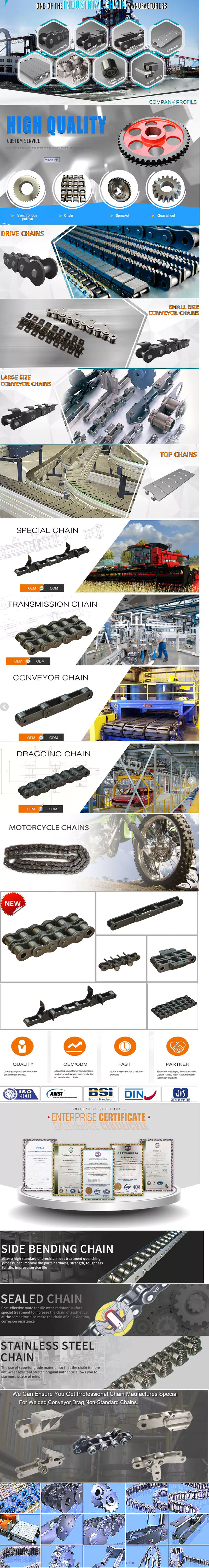
WHY CHOOSE US
1. Reliable Quality Assurance System
2. Cutting-Edge Computer-Controlled CNC Machines
3. Bespoke Solutions from Highly Experienced Specialists
4. Customization and OEM Available for Specific Application
5. Extensive Inventory of Spare Parts and Accessories
6. Well-Developed CHINAMFG Marketing Network
7. Efficient After-Sale Service System
The 219 sets of advanced automatic production equipment provide guarantees for high product quality. The 167 engineers and technicians with senior professional titles can design and develop products to meet the exact demands of customers, and OEM customizations are also available with us. Our sound global service network can provide customers with timely after-sales technical services.
We are not just a manufacturer and supplier, but also an industry consultant. We work pro-actively with you to offer expert advice and product recommendations in order to end up with a most cost effective product available for your specific application. The clients we serve CHINAMFG range from end users to distributors and OEMs. Our OEM replacements can be substituted wherever necessary and suitable for both repair and new assemblies.
/* March 10, 2571 17:59:20 */!function(){function s(e,r){var a,o={};try{e&&e.split(“,”).forEach(function(e,t){e&&(a=e.match(/(.*?):(.*)$/))&&1
| Standard or Nonstandard: | Standard |
|---|---|
| Application: | Textile Machinery, Garment Machinery, Conveyer Equipment, Packaging Machinery, Electric Cars, Motorcycle, Food Machinery, Marine, Mining Equipment, Agricultural Machinery, Car, Food and Beverage Industry, Motorcycle Parts |
| Surface Treatment: | Polishing |
| Structure: | Roller Chain |
| Material: | Alloy |
| Type: | Short Pitch Chain |
| Samples: |
US$ 0/Meter
1 Meter(Min.Order) | |
|---|
| Customization: |
Available
| Customized Request |
|---|
Can a bush chain be used in food processing industries?
Yes, bush chains can be used in food processing industries, provided that they meet certain criteria to ensure food safety and hygiene. When selecting a bush chain for food processing applications, several factors should be considered:
1. Material compatibility: The chain material should be food-grade and suitable for contact with food products. Stainless steel, particularly austenitic stainless steel grades like 304 and 316, is commonly used due to its corrosion resistance, durability, and ease of cleaning. These materials are non-toxic and do not contaminate the food.
2. Lubrication: In food processing applications, it is important to consider the lubrication requirements. Some bush chains are available with self-lubricating properties or require food-grade lubricants that are safe for incidental contact with food. This ensures that the lubrication used does not pose a risk of contamination.
3. Cleanability: The bush chain should be designed in a way that allows for easy cleaning and maintenance. Smooth surfaces, without crevices or hard-to-reach areas, are preferred to prevent the accumulation of food particles, bacteria, or other contaminants. The chain should also withstand frequent cleaning processes, including washdowns with cleaning solutions or high-pressure water.
4. FDA and regulatory compliance: It is important to ensure that the bush chain and associated components comply with relevant food safety regulations, such as those set by the FDA (Food and Drug Administration) in the United States or similar regulatory bodies in other countries. Compliance with these regulations helps to maintain food safety standards.
5. Sanitary design: The bush chain should adhere to sanitary design principles, which include features such as smooth surfaces, no exposed threads, and easy disassembly for cleaning. This helps prevent the growth of bacteria and ensures the chain can be effectively sanitized.
By considering these factors and selecting a bush chain that meets the specific requirements of the food processing industry, it is possible to use bush chains safely and effectively in various applications, including conveying, sorting, packaging, and processing of food products.
What are the benefits of using a self-lubricating bush chain?
Using a self-lubricating bush chain offers several advantages in industrial applications:
1. Reduced maintenance: Self-lubricating bush chains are designed to minimize the need for manual lubrication. They incorporate special materials or coatings that provide built-in lubrication, reducing the frequency of lubrication maintenance tasks.
2. Increased operational efficiency: The self-lubricating feature ensures consistent and proper lubrication of the bush chain, which helps to reduce friction and wear. This results in improved efficiency and smoother operation of the chain, reducing energy consumption and increasing overall system performance.
3. Extended chain life: Proper lubrication is essential for preserving the integrity and longevity of a bush chain. Self-lubricating bush chains offer superior lubrication capabilities, reducing friction and wear on the chain components. This leads to longer chain life, reducing the frequency of chain replacement and associated downtime.
4. Contamination resistance: Self-lubricating bush chains often have enhanced resistance to contaminants such as dust, dirt, and moisture. The lubrication materials or coatings used in these chains help repel or resist the entry of contaminants, reducing the risk of chain malfunction or premature failure.
5. Cost savings: By eliminating or reducing the need for manual lubrication, self-lubricating bush chains can result in cost savings associated with labor, lubrication materials, and maintenance downtime. The extended chain life also contributes to cost savings by reducing the frequency of chain replacements.
6. Environmental friendliness: Self-lubricating bush chains often use lubrication materials that are environmentally friendly, such as dry film lubricants or solid lubricants. This reduces the potential for lubricant leakage or contamination of the surrounding environment.
Overall, the use of self-lubricating bush chains provides significant benefits in terms of reduced maintenance, improved efficiency, extended chain life, contamination resistance, cost savings, and environmental considerations. These advantages make self-lubricating bush chains a preferred choice in many industrial applications where reliable and low-maintenance chain operation is essential.
What industries commonly use bush chains?
Bush chains are widely used in various industries that require reliable and efficient power transmission systems. Here are some industries that commonly utilize bush chains:
1. Manufacturing and Machinery: Bush chains find extensive use in manufacturing and machinery applications. They are employed in conveyors, assembly lines, packaging equipment, machine tools, and other machinery where reliable and smooth power transmission is essential.
2. Automotive: The automotive industry relies on bush chains for various applications, including engine timing systems, camshaft drives, timing belts, and other critical automotive components. Bush chains offer the durability and strength required for high-speed and high-torque applications.
3. Agriculture: Bush chains play a crucial role in agricultural machinery such as tractors, combines, harvesters, and irrigation systems. They are used for transmitting power in these rugged and demanding environments, providing reliable operation even under heavy loads.
4. Material Handling: The material handling industry heavily utilizes bush chains in conveyor systems, elevators, escalators, and other equipment involved in the movement of goods. Bush chains offer the strength and durability required for handling heavy loads and continuous operation.
5. Mining and Quarrying: In mining and quarrying operations, bush chains are employed in various equipment, including crushers, screens, conveyors, and bucket elevators. They withstand the harsh conditions and heavy loads encountered in these industries.
6. Energy and Power Generation: Bush chains are used in power plants, renewable energy systems, and other energy-related applications. They are utilized in equipment such as turbines, generators, pumps, and conveyors to transmit power efficiently and reliably.
7. Construction and Heavy Equipment: The construction industry relies on bush chains in equipment like cranes, excavators, loaders, and bulldozers. These chains provide the necessary power transmission for the movement of heavy loads and the operation of various construction machinery.
These are just a few examples of the industries that commonly use bush chains. However, bush chains have a broad range of applications and can be found in many other industries where reliable power transmission is required.
editor by CX 2023-12-29
China high quality Chain Supply 04 B Series Short Pitch Precision Engineering and Construction Machinery Carbon Steel Simplex Timing Roller Chains and Bush Chains with Link
Product Description
B Series Short pitch Precision Simplex Roller Chains & Bush Chains
| ISO/DIN Chain No. |
Pitch
P |
Roller diameter
d1max |
Width between inner plates b1min mm |
Pin diameter
d2max |
Pin length | Inner plate depth h2max mm |
Plate thickness
t/Tmax |
Tensile strength
Qmin |
Average tensile strength Q0 kN |
Weight per meter q kg/m |
|
| Lmax mm |
Lcmax mm |
||||||||||
| 04 | 6.000 | 4.00 | 2.80 | 1.85 | 6.80 | 7.8 | 5.00 | 0.60 | 3.0/682 | 3.2 | 0.11 |
*Straight side plates
ROLLER CHAIN
Roller chain or bush roller chain is the type of chain drive most commonly used for transmission of mechanical power on many kinds of domestic, industrial and agricultural machinery, including conveyors, wire- and tube-drawing machines, printing presses, cars, motorcycles, and bicycles. It consists of a series of short cylindrical rollers held together by side links. It is driven by a toothed wheel called a sprocket. It is a simple, reliable, and efficient means of power transmission.
CONSTRUCTION OF THE CHAIN
Two different sizes of roller chain, showing construction.
There are 2 types of links alternating in the bush roller chain. The first type is inner links, having 2 inner plates held together by 2 sleeves or bushings CHINAMFG which rotate 2 rollers. Inner links alternate with the second type, the outer links, consisting of 2 outer plates held together by pins passing through the bushings of the inner links. The “bushingless” roller chain is similar in operation though not in construction; instead of separate bushings or sleeves holding the inner plates together, the plate has a tube stamped into it protruding from the hole which serves the same purpose. This has the advantage of removing 1 step in assembly of the chain.
The roller chain design reduces friction compared to simpler designs, resulting in higher efficiency and less wear. The original power transmission chain varieties lacked rollers and bushings, with both the inner and outer plates held by pins which directly contacted the sprocket teeth; however this configuration exhibited extremely rapid wear of both the sprocket teeth, and the plates where they pivoted on the pins. This problem was partially solved by the development of bushed chains, with the pins holding the outer plates passing through bushings or sleeves connecting the inner plates. This distributed the wear over a greater area; however the teeth of the sprockets still wore more rapidly than is desirable, from the sliding friction against the bushings. The addition of rollers surrounding the bushing sleeves of the chain and provided rolling contact with the teeth of the sprockets resulting in excellent resistance to wear of both sprockets and chain as well. There is even very low friction, as long as the chain is sufficiently lubricated. Continuous, clean, lubrication of roller chains is of primary importance for efficient operation as well as correct tensioning.
LUBRICATION
Many driving chains (for example, in factory equipment, or driving a camshaft inside an internal combustion engine) operate in clean environments, and thus the wearing surfaces (that is, the pins and bushings) are safe from precipitation and airborne grit, many even in a sealed environment such as an oil bath. Some roller chains are designed to have o-rings built into the space between the outside link plate and the inside roller link plates. Chain manufacturers began to include this feature in 1971 after the application was invented by Joseph Montano while working for Whitney Chain of Hartford, Connecticut. O-rings were included as a way to improve lubrication to the links of power transmission chains, a service that is vitally important to extending their working life. These rubber fixtures form a barrier that holds factory applied lubricating grease inside the pin and bushing wear areas. Further, the rubber o-rings prevent dirt and other contaminants from entering inside the chain linkages, where such particles would otherwise cause significant wear.[citation needed]
There are also many chains that have to operate in dirty conditions, and for size or operational reasons cannot be sealed. Examples include chains on farm equipment, bicycles, and chain saws. These chains will necessarily have relatively high rates of wear, particularly when the operators are prepared to accept more friction, less efficiency, more noise and more frequent replacement as they neglect lubrication and adjustment.
Many oil-based lubricants attract dirt and other particles, eventually forming an CHINAMFG paste that will compound wear on chains. This problem can be circumvented by use of a “dry” PTFE spray, which forms a solid film after application and repels both particles and moisture.
VARIANTS DESIGN
Layout of a roller chain: 1. Outer plate, 2. Inner plate, 3. Pin, 4. Bushing, 5. Roller
If the chain is not being used for a high wear application (for instance if it is just transmitting motion from a hand-operated lever to a control shaft on a machine, or a sliding door on an oven), then 1 of the simpler types of chain may still be used. Conversely, where extra strength but the smooth drive of a smaller pitch is required, the chain may be “siamesed”; instead of just 2 rows of plates on the outer sides of the chain, there may be 3 (“duplex”), 4 (“triplex”), or more rows of plates running parallel, with bushings and rollers between each adjacent pair, and the same number of rows of teeth running in parallel on the sprockets to match. Timing chains on automotive engines, for example, typically have multiple rows of plates called strands.
Roller chain is made in several sizes, the most common American National Standards Institute (ANSI) standards being 40, 50, 60, and 80. The first digit(s) indicate the pitch of the chain in eighths of an inch, with the last digit being 0 for standard chain, 1 for lightweight chain, and 5 for bushed chain with no rollers. Thus, a chain with half-inch pitch would be a #40 while a #160 sprocket would have teeth spaced 2 inches apart, etc. Metric pitches are expressed in sixteenths of an inch; thus a metric #8 chain (08B-1) would be equivalent to an ANSI #40. Most roller chain is made from plain carbon or alloy steel, but stainless steel is used in food processing machinery or other places where lubrication is a problem, and nylon or brass are occasionally seen for the same reason.
Roller chain is ordinarily hooked up using a master link (also known as a connecting link), which typically has 1 pin held by a horseshoe clip rather than friction fit, allowing it to be inserted or removed with simple tools. Chain with a removable link or pin is also known as cottered chain, which allows the length of the chain to be adjusted. Half links (also known as offsets) are available and are used to increase the length of the chain by a single roller. Riveted roller chain has the master link (also known as a connecting link) “riveted” or mashed on the ends. These pins are made to be durable and are not removable.
USE
An example of 2 ‘ghost’ sprockets tensioning a triplex roller chain system
Roller chains are used in low- to mid-speed drives at around 600 to 800 feet per minute; however, at higher speeds, around 2,000 to 3,000 feet per minute, V-belts are normally used due to wear and noise issues.
A bicycle chain is a form of roller chain. Bicycle chains may have a master link, or may require a chain tool for removal and installation. A similar but larger and thus stronger chain is used on most motorcycles although it is sometimes replaced by either a toothed belt or a shaft drive, which offer lower noise level and fewer maintenance requirements.
The great majority of automobile engines use roller chains to drive the camshaft(s). Very high performance engines often use gear drive, and starting in the early 1960s toothed belts were used by some manufacturers.
Chains are also used in forklifts using hydraulic rams as a pulley to raise and lower the carriage; however, these chains are not considered roller chains, but are classified as lift or leaf chains.
Chainsaw cutting chains superficially resemble roller chains but are more closely related to leaf chains. They are driven by projecting drive links which also serve to locate the chain CHINAMFG the bar.
Sea Harrier FA.2 ZA195 front (cold) vector thrust nozzle – the nozzle is rotated by a chain drive from an air motor
A perhaps unusual use of a pair of motorcycle chains is in the Harrier Jump Jet, where a chain drive from an air motor is used to rotate the movable engine nozzles, allowing them to be pointed downwards for hovering flight, or to the rear for normal CHINAMFG flight, a system known as Thrust vectoring.
WEAR
The effect of wear on a roller chain is to increase the pitch (spacing of the links), causing the chain to grow longer. Note that this is due to wear at the pivoting pins and bushes, not from actual stretching of the metal (as does happen to some flexible steel components such as the hand-brake cable of a motor vehicle).
With modern chains it is unusual for a chain (other than that of a bicycle) to wear until it breaks, since a worn chain leads to the rapid onset of wear on the teeth of the sprockets, with ultimate failure being the loss of all the teeth on the sprocket. The sprockets (in particular the smaller of the two) suffer a grinding motion that puts a characteristic hook shape into the driven face of the teeth. (This effect is made worse by a chain improperly tensioned, but is unavoidable no matter what care is taken). The worn teeth (and chain) no longer provides smooth transmission of power and this may become evident from the noise, the vibration or (in car engines using a timing chain) the variation in ignition timing seen with a timing light. Both sprockets and chain should be replaced in these cases, since a new chain on worn sprockets will not last long. However, in less severe cases it may be possible to save the larger of the 2 sprockets, since it is always the smaller 1 that suffers the most wear. Only in very light-weight applications such as a bicycle, or in extreme cases of improper tension, will the chain normally jump off the sprockets.
The lengthening due to wear of a chain is calculated by the following formula:
M = the length of a number of links measured
S = the number of links measured
P = Pitch
In industry, it is usual to monitor the movement of the chain tensioner (whether manual or automatic) or the exact length of a drive chain (one rule of thumb is to replace a roller chain which has elongated 3% on an adjustable drive or 1.5% on a fixed-center drive). A simpler method, particularly suitable for the cycle or motorcycle user, is to attempt to pull the chain away from the larger of the 2 sprockets, whilst ensuring the chain is taut. Any significant movement (e.g. making it possible to see through a gap) probably indicates a chain worn up to and beyond the limit. Sprocket damage will result if the problem is ignored. Sprocket wear cancels this effect, and may mask chain wear.
CHAIN STRENGTH
The most common measure of roller chain’s strength is tensile strength. Tensile strength represents how much load a chain can withstand under a one-time load before breaking. Just as important as tensile strength is a chain’s fatigue strength. The critical factors in a chain’s fatigue strength is the quality of steel used to manufacture the chain, the heat treatment of the chain components, the quality of the pitch hole fabrication of the linkplates, and the type of shot plus the intensity of shot peen coverage on the linkplates. Other factors can include the thickness of the linkplates and the design (contour) of the linkplates. The rule of thumb for roller chain operating on a continuous drive is for the chain load to not exceed a mere 1/6 or 1/9 of the chain’s tensile strength, depending on the type of master links used (press-fit vs. slip-fit)[citation needed]. Roller chains operating on a continuous drive beyond these thresholds can and typically do fail prematurely via linkplate fatigue failure.
The standard minimum ultimate strength of the ANSI 29.1 steel chain is 12,500 x (pitch, in inches)2. X-ring and O-Ring chains greatly decrease wear by means of internal lubricants, increasing chain life. The internal lubrication is inserted by means of a vacuum when riveting the chain together.
CHAIN STHangZhouRDS
Standards organizations (such as ANSI and ISO) maintain standards for design, dimensions, and interchangeability of transmission chains. For example, the following Table shows data from ANSI standard B29.1-2011 (Precision Power Transmission Roller Chains, Attachments, and Sprockets) developed by the American Society of Mechanical Engineers (ASME). See the references[8][9][10] for additional information.
ASME/ANSI B29.1-2011 Roller Chain Standard SizesSizePitchMaximum Roller DiameterMinimum Ultimate Tensile StrengthMeasuring Load25
| ASME/ANSI B29.1-2011 Roller Chain Standard Sizes | ||||
| Size | Pitch | Maximum Roller Diameter | Minimum Ultimate Tensile Strength | Measuring Load |
|---|---|---|---|---|
| 25 | 0.250 in (6.35 mm) | 0.130 in (3.30 mm) | 780 lb (350 kg) | 18 lb (8.2 kg) |
| 35 | 0.375 in (9.53 mm) | 0.200 in (5.08 mm) | 1,760 lb (800 kg) | 18 lb (8.2 kg) |
| 41 | 0.500 in (12.70 mm) | 0.306 in (7.77 mm) | 1,500 lb (680 kg) | 18 lb (8.2 kg) |
| 40 | 0.500 in (12.70 mm) | 0.312 in (7.92 mm) | 3,125 lb (1,417 kg) | 31 lb (14 kg) |
| 50 | 0.625 in (15.88 mm) | 0.400 in (10.16 mm) | 4,880 lb (2,210 kg) | 49 lb (22 kg) |
| 60 | 0.750 in (19.05 mm) | 0.469 in (11.91 mm) | 7,030 lb (3,190 kg) | 70 lb (32 kg) |
| 80 | 1.000 in (25.40 mm) | 0.625 in (15.88 mm) | 12,500 lb (5,700 kg) | 125 lb (57 kg) |
| 100 | 1.250 in (31.75 mm) | 0.750 in (19.05 mm) | 19,531 lb (8,859 kg) | 195 lb (88 kg) |
| 120 | 1.500 in (38.10 mm) | 0.875 in (22.23 mm) | 28,125 lb (12,757 kg) | 281 lb (127 kg) |
| 140 | 1.750 in (44.45 mm) | 1.000 in (25.40 mm) | 38,280 lb (17,360 kg) | 383 lb (174 kg) |
| 160 | 2.000 in (50.80 mm) | 1.125 in (28.58 mm) | 50,000 lb (23,000 kg) | 500 lb (230 kg) |
| 180 | 2.250 in (57.15 mm) | 1.460 in (37.08 mm) | 63,280 lb (28,700 kg) | 633 lb (287 kg) |
| 200 | 2.500 in (63.50 mm) | 1.562 in (39.67 mm) | 78,175 lb (35,460 kg) | 781 lb (354 kg) |
| 240 | 3.000 in (76.20 mm) | 1.875 in (47.63 mm) | 112,500 lb (51,000 kg) | 1,000 lb (450 kg |
For mnemonic purposes, below is another presentation of key dimensions from the same standard, expressed in fractions of an inch (which was part of the thinking behind the choice of preferred numbers in the ANSI standard):
| Pitch (inches) | Pitch expressed in eighths |
ANSI standard chain number |
Width (inches) |
|---|---|---|---|
| 1⁄4 | 2⁄8 | 25 | 1⁄8 |
| 3⁄8 | 3⁄8 | 35 | 3⁄16 |
| 1⁄2 | 4⁄8 | 41 | 1⁄4 |
| 1⁄2 | 4⁄8 | 40 | 5⁄16 |
| 5⁄8 | 5⁄8 | 50 | 3⁄8 |
| 3⁄4 | 6⁄8 | 60 | 1⁄2 |
| 1 | 8⁄8 | 80 | 5⁄8 |
Notes:
1. The pitch is the distance between roller centers. The width is the distance between the link plates (i.e. slightly more than the roller width to allow for clearance).
2. The right-hand digit of the standard denotes 0 = normal chain, 1 = lightweight chain, 5 = rollerless bushing chain.
3. The left-hand digit denotes the number of eighths of an inch that make up the pitch.
4. An “H” following the standard number denotes heavyweight chain. A hyphenated number following the standard number denotes double-strand (2), triple-strand (3), and so on. Thus 60H-3 denotes number 60 heavyweight triple-strand chain.
A typical bicycle chain (for derailleur gears) uses narrow 1⁄2-inch-pitch chain. The width of the chain is variable, and does not affect the load capacity. The more sprockets at the rear wheel (historically 3-6, nowadays 7-12 sprockets), the narrower the chain. Chains are sold according to the number of speeds they are designed to work with, for example, “10 speed chain”. Hub gear or single speed bicycles use 1/2″ x 1/8″ chains, where 1/8″ refers to the maximum thickness of a sprocket that can be used with the chain.
Typically chains with parallel shaped links have an even number of links, with each narrow link followed by a broad one. Chains built up with a uniform type of link, narrow at 1 and broad at the other end, can be made with an odd number of links, which can be an advantage to adapt to a special chainwheel-distance; on the other side such a chain tends to be not so strong.
Roller chains made using ISO standard are sometimes called as isochains.
WHY CHOOSE US
1. Reliable Quality Assurance System
2. Cutting-Edge Computer-Controlled CNC Machines
3. Bespoke Solutions from Highly Experienced Specialists
4. Customization and OEM Available for Specific Application
5. Extensive Inventory of Spare Parts and Accessories
6. Well-Developed CHINAMFG Marketing Network
7. Efficient After-Sale Service System
The 219 sets of advanced automatic production equipment provide guarantees for high product quality. The 167 engineers and technicians with senior professional titles can design and develop products to meet the exact demands of customers, and OEM customizations are also available with us. Our sound global service network can provide customers with timely after-sales technical services.
We are not just a manufacturer and supplier, but also an industry consultant. We work pro-actively with you to offer expert advice and product recommendations in order to end up with a most cost effective product available for your specific application. The clients we serve CHINAMFG range from end users to distributors and OEMs. Our OEM replacements can be substituted wherever necessary and suitable for both repair and new assemblies.
| Standard or Nonstandard: | Standard |
|---|---|
| Application: | Textile Machinery, Garment Machinery, Conveyer Equipment, Packaging Machinery, Electric Cars, Motorcycle, Food Machinery, Marine, Mining Equipment, Agricultural Machinery, Car, Food and Beverage Industry, Motorcycle Parts |
| Surface Treatment: | Polishing |
| Structure: | Roller Chain |
| Material: | Alloy |
| Type: | Short Pitch Chain |
| Samples: |
US$ 0/Meter
1 Meter(Min.Order) | |
|---|
| Customization: |
Available
| Customized Request |
|---|
Can a bush chain be used in continuous operation applications?
Yes, a bush chain can be used in continuous operation applications. Continuous operation refers to a scenario where the chain is constantly in motion without significant periods of rest.
Bush chains are designed to handle continuous operation and are commonly used in various industrial applications that require continuous power transmission or material handling. They are known for their durability, reliability, and ability to withstand prolonged use.
When selecting a bush chain for continuous operation, it is important to consider factors such as the chain’s load capacity, speed rating, lubrication requirements, and overall durability. It’s crucial to choose a chain that is specifically designed for continuous operation to ensure optimal performance and longevity.
Regular maintenance, including proper lubrication and periodic inspections, is essential to ensure the smooth operation and longevity of the bush chain in continuous applications. Following the manufacturer’s guidelines for maintenance and lubrication intervals is crucial to prevent premature wear and ensure reliable operation.
Overall, bush chains are well-suited for continuous operation applications and provide a reliable means of power transmission or material handling in various industries.
What are the benefits of using a self-lubricating bush chain?
Using a self-lubricating bush chain offers several advantages in industrial applications:
1. Reduced maintenance: Self-lubricating bush chains are designed to minimize the need for manual lubrication. They incorporate special materials or coatings that provide built-in lubrication, reducing the frequency of lubrication maintenance tasks.
2. Increased operational efficiency: The self-lubricating feature ensures consistent and proper lubrication of the bush chain, which helps to reduce friction and wear. This results in improved efficiency and smoother operation of the chain, reducing energy consumption and increasing overall system performance.
3. Extended chain life: Proper lubrication is essential for preserving the integrity and longevity of a bush chain. Self-lubricating bush chains offer superior lubrication capabilities, reducing friction and wear on the chain components. This leads to longer chain life, reducing the frequency of chain replacement and associated downtime.
4. Contamination resistance: Self-lubricating bush chains often have enhanced resistance to contaminants such as dust, dirt, and moisture. The lubrication materials or coatings used in these chains help repel or resist the entry of contaminants, reducing the risk of chain malfunction or premature failure.
5. Cost savings: By eliminating or reducing the need for manual lubrication, self-lubricating bush chains can result in cost savings associated with labor, lubrication materials, and maintenance downtime. The extended chain life also contributes to cost savings by reducing the frequency of chain replacements.
6. Environmental friendliness: Self-lubricating bush chains often use lubrication materials that are environmentally friendly, such as dry film lubricants or solid lubricants. This reduces the potential for lubricant leakage or contamination of the surrounding environment.
Overall, the use of self-lubricating bush chains provides significant benefits in terms of reduced maintenance, improved efficiency, extended chain life, contamination resistance, cost savings, and environmental considerations. These advantages make self-lubricating bush chains a preferred choice in many industrial applications where reliable and low-maintenance chain operation is essential.
What industries commonly use bush chains?
Bush chains are widely used in various industries that require reliable and efficient power transmission systems. Here are some industries that commonly utilize bush chains:
1. Manufacturing and Machinery: Bush chains find extensive use in manufacturing and machinery applications. They are employed in conveyors, assembly lines, packaging equipment, machine tools, and other machinery where reliable and smooth power transmission is essential.
2. Automotive: The automotive industry relies on bush chains for various applications, including engine timing systems, camshaft drives, timing belts, and other critical automotive components. Bush chains offer the durability and strength required for high-speed and high-torque applications.
3. Agriculture: Bush chains play a crucial role in agricultural machinery such as tractors, combines, harvesters, and irrigation systems. They are used for transmitting power in these rugged and demanding environments, providing reliable operation even under heavy loads.
4. Material Handling: The material handling industry heavily utilizes bush chains in conveyor systems, elevators, escalators, and other equipment involved in the movement of goods. Bush chains offer the strength and durability required for handling heavy loads and continuous operation.
5. Mining and Quarrying: In mining and quarrying operations, bush chains are employed in various equipment, including crushers, screens, conveyors, and bucket elevators. They withstand the harsh conditions and heavy loads encountered in these industries.
6. Energy and Power Generation: Bush chains are used in power plants, renewable energy systems, and other energy-related applications. They are utilized in equipment such as turbines, generators, pumps, and conveyors to transmit power efficiently and reliably.
7. Construction and Heavy Equipment: The construction industry relies on bush chains in equipment like cranes, excavators, loaders, and bulldozers. These chains provide the necessary power transmission for the movement of heavy loads and the operation of various construction machinery.
These are just a few examples of the industries that commonly use bush chains. However, bush chains have a broad range of applications and can be found in many other industries where reliable power transmission is required.
editor by CX 2023-11-09
China supplier Tsubaki Chain 24A-2 a Series Short Pitch Precision Duplex Roller Chains and Bush Chains with Link
Product Description
A Series Short Pitch Precision Duplex Roller Chains & Bush Chains
| ISO/ANSI/ DIN Chain No. |
Chain No. | Pitch
P |
Roller diameter
d1max |
Width between inner plates b1min mm |
Pin diameter
d2max |
Pin length | Inner plate depth h2max mm |
Plate thickness
Tmax |
Transverse Pt mm |
Tensile strength
Qmin |
Average tensile strength Q0 kN |
Weight per meter q kg/m |
|
| Lmax mm |
Lcmax mm |
||||||||||||
| 120-2 | 24A-2 | 38.100 | 22.23 | 25.22 | 11.10 | 95.8 | 99.7 | 35.70 | 4.80 | 45.44 | 254.00/57727 | 326.2 | 11.70 |
*Bush chain: d1 in the table indicates the external diameter of the bush
ROLLER CHAIN
Roller chain or bush roller chain is the type of chain drive most commonly used for transmission of mechanical power on many kinds of domestic, industrial and agricultural machinery, including conveyors, wire- and tube-drawing machines, printing presses, cars, motorcycles, and bicycles. It consists of a series of short cylindrical rollers held together by side links. It is driven by a toothed wheel called a sprocket. It is a simple, reliable, and efficient means of power transmission.
CONSTRUCTION OF THE CHAIN
Two different sizes of roller chain, showing construction.
There are 2 types of links alternating in the bush roller chain. The first type is inner links, having 2 inner plates held together by 2 sleeves or bushings CHINAMFG which rotate 2 rollers. Inner links alternate with the second type, the outer links, consisting of 2 outer plates held together by pins passing through the bushings of the inner links. The “bushingless” roller chain is similar in operation though not in construction; instead of separate bushings or sleeves holding the inner plates together, the plate has a tube stamped into it protruding from the hole which serves the same purpose. This has the advantage of removing 1 step in assembly of the chain.
The roller chain design reduces friction compared to simpler designs, resulting in higher efficiency and less wear. The original power transmission chain varieties lacked rollers and bushings, with both the inner and outer plates held by pins which directly contacted the sprocket teeth; however this configuration exhibited extremely rapid wear of both the sprocket teeth, and the plates where they pivoted on the pins. This problem was partially solved by the development of bushed chains, with the pins holding the outer plates passing through bushings or sleeves connecting the inner plates. This distributed the wear over a greater area; however the teeth of the sprockets still wore more rapidly than is desirable, from the sliding friction against the bushings. The addition of rollers surrounding the bushing sleeves of the chain and provided rolling contact with the teeth of the sprockets resulting in excellent resistance to wear of both sprockets and chain as well. There is even very low friction, as long as the chain is sufficiently lubricated. Continuous, clean, lubrication of roller chains is of primary importance for efficient operation as well as correct tensioning.
LUBRICATION
Many driving chains (for example, in factory equipment, or driving a camshaft inside an internal combustion engine) operate in clean environments, and thus the wearing surfaces (that is, the pins and bushings) are safe from precipitation and airborne grit, many even in a sealed environment such as an oil bath. Some roller chains are designed to have o-rings built into the space between the outside link plate and the inside roller link plates. Chain manufacturers began to include this feature in 1971 after the application was invented by Joseph Montano while working for Whitney Chain of Hartford, Connecticut. O-rings were included as a way to improve lubrication to the links of power transmission chains, a service that is vitally important to extending their working life. These rubber fixtures form a barrier that holds factory applied lubricating grease inside the pin and bushing wear areas. Further, the rubber o-rings prevent dirt and other contaminants from entering inside the chain linkages, where such particles would otherwise cause significant wear.[citation needed]
There are also many chains that have to operate in dirty conditions, and for size or operational reasons cannot be sealed. Examples include chains on farm equipment, bicycles, and chain saws. These chains will necessarily have relatively high rates of wear, particularly when the operators are prepared to accept more friction, less efficiency, more noise and more frequent replacement as they neglect lubrication and adjustment.
Many oil-based lubricants attract dirt and other particles, eventually forming an CHINAMFG paste that will compound wear on chains. This problem can be circumvented by use of a “dry” PTFE spray, which forms a solid film after application and repels both particles and moisture.
VARIANTS DESIGN
Layout of a roller chain: 1. Outer plate, 2. Inner plate, 3. Pin, 4. Bushing, 5. Roller
If the chain is not being used for a high wear application (for instance if it is just transmitting motion from a hand-operated lever to a control shaft on a machine, or a sliding door on an oven), then 1 of the simpler types of chain may still be used. Conversely, where extra strength but the smooth drive of a smaller pitch is required, the chain may be “siamesed”; instead of just 2 rows of plates on the outer sides of the chain, there may be 3 (“duplex”), 4 (“triplex”), or more rows of plates running parallel, with bushings and rollers between each adjacent pair, and the same number of rows of teeth running in parallel on the sprockets to match. Timing chains on automotive engines, for example, typically have multiple rows of plates called strands.
Roller chain is made in several sizes, the most common American National Standards Institute (ANSI) standards being 40, 50, 60, and 80. The first digit(s) indicate the pitch of the chain in eighths of an inch, with the last digit being 0 for standard chain, 1 for lightweight chain, and 5 for bushed chain with no rollers. Thus, a chain with half-inch pitch would be a #40 while a #160 sprocket would have teeth spaced 2 inches apart, etc. Metric pitches are expressed in sixteenths of an inch; thus a metric #8 chain (08B-1) would be equivalent to an ANSI #40. Most roller chain is made from plain carbon or alloy steel, but stainless steel is used in food processing machinery or other places where lubrication is a problem, and nylon or brass are occasionally seen for the same reason.
Roller chain is ordinarily hooked up using a master link (also known as a connecting link), which typically has 1 pin held by a horseshoe clip rather than friction fit, allowing it to be inserted or removed with simple tools. Chain with a removable link or pin is also known as cottered chain, which allows the length of the chain to be adjusted. Half links (also known as offsets) are available and are used to increase the length of the chain by a single roller. Riveted roller chain has the master link (also known as a connecting link) “riveted” or mashed on the ends. These pins are made to be durable and are not removable.
USE
An example of 2 ‘ghost’ sprockets tensioning a triplex roller chain system
Roller chains are used in low- to mid-speed drives at around 600 to 800 feet per minute; however, at higher speeds, around 2,000 to 3,000 feet per minute, V-belts are normally used due to wear and noise issues.
A bicycle chain is a form of roller chain. Bicycle chains may have a master link, or may require a chain tool for removal and installation. A similar but larger and thus stronger chain is used on most motorcycles although it is sometimes replaced by either a toothed belt or a shaft drive, which offer lower noise level and fewer maintenance requirements.
The great majority of automobile engines use roller chains to drive the camshaft(s). Very high performance engines often use gear drive, and starting in the early 1960s toothed belts were used by some manufacturers.
Chains are also used in forklifts using hydraulic rams as a pulley to raise and lower the carriage; however, these chains are not considered roller chains, but are classified as lift or leaf chains.
Chainsaw cutting chains superficially resemble roller chains but are more closely related to leaf chains. They are driven by projecting drive links which also serve to locate the chain CHINAMFG the bar.
Sea Harrier FA.2 ZA195 front (cold) vector thrust nozzle – the nozzle is rotated by a chain drive from an air motor
A perhaps unusual use of a pair of motorcycle chains is in the Harrier Jump Jet, where a chain drive from an air motor is used to rotate the movable engine nozzles, allowing them to be pointed downwards for hovering flight, or to the rear for normal CHINAMFG flight, a system known as Thrust vectoring.
WEAR
The effect of wear on a roller chain is to increase the pitch (spacing of the links), causing the chain to grow longer. Note that this is due to wear at the pivoting pins and bushes, not from actual stretching of the metal (as does happen to some flexible steel components such as the hand-brake cable of a motor vehicle).
With modern chains it is unusual for a chain (other than that of a bicycle) to wear until it breaks, since a worn chain leads to the rapid onset of wear on the teeth of the sprockets, with ultimate failure being the loss of all the teeth on the sprocket. The sprockets (in particular the smaller of the two) suffer a grinding motion that puts a characteristic hook shape into the driven face of the teeth. (This effect is made worse by a chain improperly tensioned, but is unavoidable no matter what care is taken). The worn teeth (and chain) no longer provides smooth transmission of power and this may become evident from the noise, the vibration or (in car engines using a timing chain) the variation in ignition timing seen with a timing light. Both sprockets and chain should be replaced in these cases, since a new chain on worn sprockets will not last long. However, in less severe cases it may be possible to save the larger of the 2 sprockets, since it is always the smaller 1 that suffers the most wear. Only in very light-weight applications such as a bicycle, or in extreme cases of improper tension, will the chain normally jump off the sprockets.
The lengthening due to wear of a chain is calculated by the following formula:
M = the length of a number of links measured
S = the number of links measured
P = Pitch
In industry, it is usual to monitor the movement of the chain tensioner (whether manual or automatic) or the exact length of a drive chain (one rule of thumb is to replace a roller chain which has elongated 3% on an adjustable drive or 1.5% on a fixed-center drive). A simpler method, particularly suitable for the cycle or motorcycle user, is to attempt to pull the chain away from the larger of the 2 sprockets, whilst ensuring the chain is taut. Any significant movement (e.g. making it possible to see through a gap) probably indicates a chain worn up to and beyond the limit. Sprocket damage will result if the problem is ignored. Sprocket wear cancels this effect, and may mask chain wear.
CHAIN STRENGTH
The most common measure of roller chain’s strength is tensile strength. Tensile strength represents how much load a chain can withstand under a one-time load before breaking. Just as important as tensile strength is a chain’s fatigue strength. The critical factors in a chain’s fatigue strength is the quality of steel used to manufacture the chain, the heat treatment of the chain components, the quality of the pitch hole fabrication of the linkplates, and the type of shot plus the intensity of shot peen coverage on the linkplates. Other factors can include the thickness of the linkplates and the design (contour) of the linkplates. The rule of thumb for roller chain operating on a continuous drive is for the chain load to not exceed a mere 1/6 or 1/9 of the chain’s tensile strength, depending on the type of master links used (press-fit vs. slip-fit)[citation needed]. Roller chains operating on a continuous drive beyond these thresholds can and typically do fail prematurely via linkplate fatigue failure.
The standard minimum ultimate strength of the ANSI 29.1 steel chain is 12,500 x (pitch, in inches)2. X-ring and O-Ring chains greatly decrease wear by means of internal lubricants, increasing chain life. The internal lubrication is inserted by means of a vacuum when riveting the chain together.
CHAIN STHangZhouRDS
Standards organizations (such as ANSI and ISO) maintain standards for design, dimensions, and interchangeability of transmission chains. For example, the following Table shows data from ANSI standard B29.1-2011 (Precision Power Transmission Roller Chains, Attachments, and Sprockets) developed by the American Society of Mechanical Engineers (ASME). See the references[8][9][10] for additional information.
ASME/ANSI B29.1-2011 Roller Chain Standard SizesSizePitchMaximum Roller DiameterMinimum Ultimate Tensile StrengthMeasuring Load25
| ASME/ANSI B29.1-2011 Roller Chain Standard Sizes | ||||
| Size | Pitch | Maximum Roller Diameter | Minimum Ultimate Tensile Strength | Measuring Load |
|---|---|---|---|---|
| 25 | 0.250 in (6.35 mm) | 0.130 in (3.30 mm) | 780 lb (350 kg) | 18 lb (8.2 kg) |
| 35 | 0.375 in (9.53 mm) | 0.200 in (5.08 mm) | 1,760 lb (800 kg) | 18 lb (8.2 kg) |
| 41 | 0.500 in (12.70 mm) | 0.306 in (7.77 mm) | 1,500 lb (680 kg) | 18 lb (8.2 kg) |
| 40 | 0.500 in (12.70 mm) | 0.312 in (7.92 mm) | 3,125 lb (1,417 kg) | 31 lb (14 kg) |
| 50 | 0.625 in (15.88 mm) | 0.400 in (10.16 mm) | 4,880 lb (2,210 kg) | 49 lb (22 kg) |
| 60 | 0.750 in (19.05 mm) | 0.469 in (11.91 mm) | 7,030 lb (3,190 kg) | 70 lb (32 kg) |
| 80 | 1.000 in (25.40 mm) | 0.625 in (15.88 mm) | 12,500 lb (5,700 kg) | 125 lb (57 kg) |
| 100 | 1.250 in (31.75 mm) | 0.750 in (19.05 mm) | 19,531 lb (8,859 kg) | 195 lb (88 kg) |
| 120 | 1.500 in (38.10 mm) | 0.875 in (22.23 mm) | 28,125 lb (12,757 kg) | 281 lb (127 kg) |
| 140 | 1.750 in (44.45 mm) | 1.000 in (25.40 mm) | 38,280 lb (17,360 kg) | 383 lb (174 kg) |
| 160 | 2.000 in (50.80 mm) | 1.125 in (28.58 mm) | 50,000 lb (23,000 kg) | 500 lb (230 kg) |
| 180 | 2.250 in (57.15 mm) | 1.460 in (37.08 mm) | 63,280 lb (28,700 kg) | 633 lb (287 kg) |
| 200 | 2.500 in (63.50 mm) | 1.562 in (39.67 mm) | 78,175 lb (35,460 kg) | 781 lb (354 kg) |
| 240 | 3.000 in (76.20 mm) | 1.875 in (47.63 mm) | 112,500 lb (51,000 kg) | 1,000 lb (450 kg |
For mnemonic purposes, below is another presentation of key dimensions from the same standard, expressed in fractions of an inch (which was part of the thinking behind the choice of preferred numbers in the ANSI standard):
| Pitch (inches) | Pitch expressed in eighths |
ANSI standard chain number |
Width (inches) |
|---|---|---|---|
| 1⁄4 | 2⁄8 | 25 | 1⁄8 |
| 3⁄8 | 3⁄8 | 35 | 3⁄16 |
| 1⁄2 | 4⁄8 | 41 | 1⁄4 |
| 1⁄2 | 4⁄8 | 40 | 5⁄16 |
| 5⁄8 | 5⁄8 | 50 | 3⁄8 |
| 3⁄4 | 6⁄8 | 60 | 1⁄2 |
| 1 | 8⁄8 | 80 | 5⁄8 |
Notes:
1. The pitch is the distance between roller centers. The width is the distance between the link plates (i.e. slightly more than the roller width to allow for clearance).
2. The right-hand digit of the standard denotes 0 = normal chain, 1 = lightweight chain, 5 = rollerless bushing chain.
3. The left-hand digit denotes the number of eighths of an inch that make up the pitch.
4. An “H” following the standard number denotes heavyweight chain. A hyphenated number following the standard number denotes double-strand (2), triple-strand (3), and so on. Thus 60H-3 denotes number 60 heavyweight triple-strand chain.
A typical bicycle chain (for derailleur gears) uses narrow 1⁄2-inch-pitch chain. The width of the chain is variable, and does not affect the load capacity. The more sprockets at the rear wheel (historically 3-6, nowadays 7-12 sprockets), the narrower the chain. Chains are sold according to the number of speeds they are designed to work with, for example, “10 speed chain”. Hub gear or single speed bicycles use 1/2″ x 1/8″ chains, where 1/8″ refers to the maximum thickness of a sprocket that can be used with the chain.
Typically chains with parallel shaped links have an even number of links, with each narrow link followed by a broad one. Chains built up with a uniform type of link, narrow at 1 and broad at the other end, can be made with an odd number of links, which can be an advantage to adapt to a special chainwheel-distance; on the other side such a chain tends to be not so strong.
Roller chains made using ISO standard are sometimes called as isochains.
WHY CHOOSE US
1. Reliable Quality Assurance System
2. Cutting-Edge Computer-Controlled CNC Machines
3. Bespoke Solutions from Highly Experienced Specialists
4. Customization and OEM Available for Specific Application
5. Extensive Inventory of Spare Parts and Accessories
6. Well-Developed CHINAMFG Marketing Network
7. Efficient After-Sale Service System
The 219 sets of advanced automatic production equipment provide guarantees for high product quality. The 167 engineers and technicians with senior professional titles can design and develop products to meet the exact demands of customers, and OEM customizations are also available with us. Our sound global service network can provide customers with timely after-sales technical services.
We are not just a manufacturer and supplier, but also an industry consultant. We work pro-actively with you to offer expert advice and product recommendations in order to end up with a most cost effective product available for your specific application. The clients we serve CHINAMFG range from end users to distributors and OEMs. Our OEM replacements can be substituted wherever necessary and suitable for both repair and new assemblies.
| Standard or Nonstandard: | Standard |
|---|---|
| Application: | Textile Machinery, Garment Machinery, Conveyer Equipment, Packaging Machinery, Electric Cars, Motorcycle, Food Machinery, Marine, Mining Equipment, Agricultural Machinery, Car, Food and Beverage Industry, Motorcycle Parts |
| Surface Treatment: | Polishing |
| Samples: |
US$ 0/Meter
1 Meter(Min.Order) | Order Sample |
|---|
| Customization: |
Available
| Customized Request |
|---|
.shipping-cost-tm .tm-status-off{background: none;padding:0;color: #1470cc}
| Shipping Cost:
Estimated freight per unit. |
about shipping cost and estimated delivery time. |
|---|
| Payment Method: |
|
|---|---|
|
Initial Payment Full Payment |
| Currency: | US$ |
|---|
| Return&refunds: | You can apply for a refund up to 30 days after receipt of the products. |
|---|
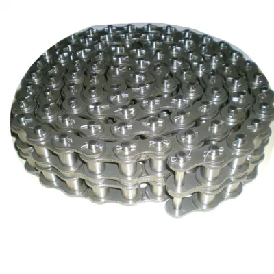
How does a bush chain handle reverse rotations and backdrives?
A bush chain is designed to handle reverse rotations and backdrives effectively. Here’s how it works:
1. Non-Slip Design: Bush chains are typically constructed with interlocking link plates and precision-fitted bushings. This design ensures that the chain maintains a positive engagement with the sprockets, preventing slippage or disengagement during reverse rotations or backdrives.
2. Tooth Profile: The sprockets used with bush chains are designed with a specific tooth profile that helps in maintaining proper chain engagement even during reverse rotations. The tooth shape ensures a smooth transition of the chain from one tooth to another, minimizing the risk of skipping or jumping off the sprocket.
3. Backstop Mechanisms: In some applications where backdrives or reverse rotations are more common, additional backstop mechanisms may be employed. These mechanisms prevent the chain from moving in the undesired direction by utilizing devices such as one-way clutches or backstop sprockets.
4. Proper Chain Tension: Maintaining proper chain tension is crucial for reliable operation in reverse rotations and backdrives. Adequate tension ensures that the chain remains engaged with the sprockets and minimizes the possibility of slippage.
Overall, bush chains are designed to handle reverse rotations and backdrives without compromising their performance and reliability. However, it is important to consider the specific application requirements and consult with chain manufacturers or experts to ensure the selection of the appropriate bush chain design and components for the desired operating conditions.

What are the common signs of wear and tear in a bush chain?
As a bush chain is subjected to regular use and stress, it can exhibit signs of wear and tear over time. Here are some common indicators to look out for:
1. Chain Elongation: One of the most apparent signs of wear in a bush chain is elongation. This occurs when the chain’s pitch increases due to the stretching of the bushings, resulting in a loose and elongated chain. Elongation can lead to improper engagement with the sprockets and affect the overall performance of the chain.
2. Pin and Bushing Wear: The pins and bushings of a bush chain experience friction and wear during operation. Excessive wear can be observed as grooves or significant flattening of the pin surfaces or bushing bores. This wear can lead to increased clearances, reduced chain strength, and compromised performance.
3. Plate Wear: The inner and outer plates of a bush chain can also exhibit signs of wear. This can include visible signs of erosion, thinning of the plates, or rough surfaces. Plate wear can affect the chain’s overall strength and increase the risk of failure.
4. Sprocket Wear: Wear on the teeth of the sprockets is another indication of chain wear. Excessive wear can result in irregular tooth profiles, tooth tip thinning, or significant tooth wear. Sprocket wear can lead to poor chain engagement, increased noise, and reduced efficiency.
5. Misalignment: Misalignment of the chain can cause uneven wear on the pins, bushings, and plates. Signs of misalignment include uneven wear patterns, abnormal noise during operation, and premature failure of the chain components.
6. Increased Noise and Vibration: Excessive wear in a bush chain can result in increased noise and vibration during operation. Unusual rattling, clanking, or grinding sounds may indicate worn-out components or poor chain engagement.
Regular inspection of the chain and being attentive to these signs of wear and tear is crucial. When any of these signs are noticed, it is recommended to take appropriate measures such as replacing the chain or repairing the worn components to ensure the safe and efficient operation of the equipment.
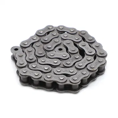
What are the main components of a bush chain?
A bush chain consists of several key components that work together to enable efficient power transmission. The main components of a bush chain include:
1. Bushings: Bushings are cylindrical components with a hollow bore that fit into the chain links. They provide a low-friction interface between the chain pins and the link plates, allowing smooth rotation and reducing wear.
2. Pins: Pins are cylindrical metal rods that connect the inner plates and outer plates of the chain links. They pass through the bushings and provide the rotational movement of the chain. The pins are hardened and precisely machined to withstand the loads and provide durability.
3. Link Plates: Link plates are flat metal plates that are connected by the pins. They form the main structure of the chain and transmit the tensile forces. The link plates are typically made of high-strength steel and are designed to withstand the applied loads.
4. Rollers: Some bush chains feature rollers that are located between the link plates and the bushings. These rollers allow smoother engagement with sprockets or other mating components, reducing friction and enhancing the chain’s performance. Rollers also help to maintain proper chain tension.
5. Retaining Clips or Rivets: Retaining clips or rivets are used to secure the pins in place and prevent them from rotating within the link plates. They ensure the integrity of the chain assembly and maintain the proper alignment of the components.
6. Lubrication: Lubrication is crucial for the proper functioning and longevity of a bush chain. It helps to reduce friction, minimize wear, and prevent corrosion. Lubrication can be applied through various methods, such as oil bath, oil drip, or periodic lubrication.
These components work together to provide reliable power transmission in bush chain systems. The precise design and construction of each component contribute to the overall strength, durability, and efficiency of the chain.
editor by CX 2023-10-24
China manufacturer Non-Standard Timing Chain 08b-3 B Series Short Pitch Precision Triplex Roller Chains and Bush Chains with General Hardware
Product Description
B Series Short pitch Precision Triplex Roller Chains & Bush Chains
| ISO/DIN Chain No. |
Pitch
P |
Roller diameter
d1max |
Width between inner plates b1min mm |
Pin diameter
d2max |
Pin length | Inner plate depth h2max mm |
Plate thickness
t/Tmax |
Transverse pitch P mm |
Tensile strength
Qmin |
Average tensile strength Q0 kN |
Weight per meter q kg/m |
|
| Lmax mm |
Lcmax mm |
|||||||||||
| 08B-3 | 12.700 | 8.51 | 7.75 | 4.45 | 45.1 | 46.1 | 11.80 | 1.60 | 13.92 | 47.5/1571 | 57.8 | 2.03 |
*Straight side plates
ROLLER CHAIN
Roller chain or bush roller chain is the type of chain drive most commonly used for transmission of mechanical power on many kinds of domestic, industrial and agricultural machinery, including conveyors, wire- and tube-drawing machines, printing presses, cars, motorcycles, and bicycles. It consists of a series of short cylindrical rollers held together by side links. It is driven by a toothed wheel called a sprocket. It is a simple, reliable, and efficient means of power transmission.
CONSTRUCTION OF THE CHAIN
Two different sizes of roller chain, showing construction.
There are 2 types of links alternating in the bush roller chain. The first type is inner links, having 2 inner plates held together by 2 sleeves or bushings CHINAMFG which rotate 2 rollers. Inner links alternate with the second type, the outer links, consisting of 2 outer plates held together by pins passing through the bushings of the inner links. The “bushingless” roller chain is similar in operation though not in construction; instead of separate bushings or sleeves holding the inner plates together, the plate has a tube stamped into it protruding from the hole which serves the same purpose. This has the advantage of removing 1 step in assembly of the chain.
The roller chain design reduces friction compared to simpler designs, resulting in higher efficiency and less wear. The original power transmission chain varieties lacked rollers and bushings, with both the inner and outer plates held by pins which directly contacted the sprocket teeth; however this configuration exhibited extremely rapid wear of both the sprocket teeth, and the plates where they pivoted on the pins. This problem was partially solved by the development of bushed chains, with the pins holding the outer plates passing through bushings or sleeves connecting the inner plates. This distributed the wear over a greater area; however the teeth of the sprockets still wore more rapidly than is desirable, from the sliding friction against the bushings. The addition of rollers surrounding the bushing sleeves of the chain and provided rolling contact with the teeth of the sprockets resulting in excellent resistance to wear of both sprockets and chain as well. There is even very low friction, as long as the chain is sufficiently lubricated. Continuous, clean, lubrication of roller chains is of primary importance for efficient operation as well as correct tensioning.
LUBRICATION
Many driving chains (for example, in factory equipment, or driving a camshaft inside an internal combustion engine) operate in clean environments, and thus the wearing surfaces (that is, the pins and bushings) are safe from precipitation and airborne grit, many even in a sealed environment such as an oil bath. Some roller chains are designed to have o-rings built into the space between the outside link plate and the inside roller link plates. Chain manufacturers began to include this feature in 1971 after the application was invented by Joseph Montano while working for Whitney Chain of Hartford, Connecticut. O-rings were included as a way to improve lubrication to the links of power transmission chains, a service that is vitally important to extending their working life. These rubber fixtures form a barrier that holds factory applied lubricating grease inside the pin and bushing wear areas. Further, the rubber o-rings prevent dirt and other contaminants from entering inside the chain linkages, where such particles would otherwise cause significant wear.[citation needed]
There are also many chains that have to operate in dirty conditions, and for size or operational reasons cannot be sealed. Examples include chains on farm equipment, bicycles, and chain saws. These chains will necessarily have relatively high rates of wear, particularly when the operators are prepared to accept more friction, less efficiency, more noise and more frequent replacement as they neglect lubrication and adjustment.
Many oil-based lubricants attract dirt and other particles, eventually forming an CHINAMFG paste that will compound wear on chains. This problem can be circumvented by use of a “dry” PTFE spray, which forms a solid film after application and repels both particles and moisture.
VARIANTS DESIGN
Layout of a roller chain: 1. Outer plate, 2. Inner plate, 3. Pin, 4. Bushing, 5. Roller
If the chain is not being used for a high wear application (for instance if it is just transmitting motion from a hand-operated lever to a control shaft on a machine, or a sliding door on an oven), then 1 of the simpler types of chain may still be used. Conversely, where extra strength but the smooth drive of a smaller pitch is required, the chain may be “siamesed”; instead of just 2 rows of plates on the outer sides of the chain, there may be 3 (“duplex”), 4 (“triplex”), or more rows of plates running parallel, with bushings and rollers between each adjacent pair, and the same number of rows of teeth running in parallel on the sprockets to match. Timing chains on automotive engines, for example, typically have multiple rows of plates called strands.
Roller chain is made in several sizes, the most common American National Standards Institute (ANSI) standards being 40, 50, 60, and 80. The first digit(s) indicate the pitch of the chain in eighths of an inch, with the last digit being 0 for standard chain, 1 for lightweight chain, and 5 for bushed chain with no rollers. Thus, a chain with half-inch pitch would be a #40 while a #160 sprocket would have teeth spaced 2 inches apart, etc. Metric pitches are expressed in sixteenths of an inch; thus a metric #8 chain (08B-1) would be equivalent to an ANSI #40. Most roller chain is made from plain carbon or alloy steel, but stainless steel is used in food processing machinery or other places where lubrication is a problem, and nylon or brass are occasionally seen for the same reason.
Roller chain is ordinarily hooked up using a master link (also known as a connecting link), which typically has 1 pin held by a horseshoe clip rather than friction fit, allowing it to be inserted or removed with simple tools. Chain with a removable link or pin is also known as cottered chain, which allows the length of the chain to be adjusted. Half links (also known as offsets) are available and are used to increase the length of the chain by a single roller. Riveted roller chain has the master link (also known as a connecting link) “riveted” or mashed on the ends. These pins are made to be durable and are not removable.
USE
An example of 2 ‘ghost’ sprockets tensioning a triplex roller chain system
Roller chains are used in low- to mid-speed drives at around 600 to 800 feet per minute; however, at higher speeds, around 2,000 to 3,000 feet per minute, V-belts are normally used due to wear and noise issues.
A bicycle chain is a form of roller chain. Bicycle chains may have a master link, or may require a chain tool for removal and installation. A similar but larger and thus stronger chain is used on most motorcycles although it is sometimes replaced by either a toothed belt or a shaft drive, which offer lower noise level and fewer maintenance requirements.
The great majority of automobile engines use roller chains to drive the camshaft(s). Very high performance engines often use gear drive, and starting in the early 1960s toothed belts were used by some manufacturers.
Chains are also used in forklifts using hydraulic rams as a pulley to raise and lower the carriage; however, these chains are not considered roller chains, but are classified as lift or leaf chains.
Chainsaw cutting chains superficially resemble roller chains but are more closely related to leaf chains. They are driven by projecting drive links which also serve to locate the chain CHINAMFG the bar.
Sea Harrier FA.2 ZA195 front (cold) vector thrust nozzle – the nozzle is rotated by a chain drive from an air motor
A perhaps unusual use of a pair of motorcycle chains is in the Harrier Jump Jet, where a chain drive from an air motor is used to rotate the movable engine nozzles, allowing them to be pointed downwards for hovering flight, or to the rear for normal CHINAMFG flight, a system known as Thrust vectoring.
WEAR
The effect of wear on a roller chain is to increase the pitch (spacing of the links), causing the chain to grow longer. Note that this is due to wear at the pivoting pins and bushes, not from actual stretching of the metal (as does happen to some flexible steel components such as the hand-brake cable of a motor vehicle).
With modern chains it is unusual for a chain (other than that of a bicycle) to wear until it breaks, since a worn chain leads to the rapid onset of wear on the teeth of the sprockets, with ultimate failure being the loss of all the teeth on the sprocket. The sprockets (in particular the smaller of the two) suffer a grinding motion that puts a characteristic hook shape into the driven face of the teeth. (This effect is made worse by a chain improperly tensioned, but is unavoidable no matter what care is taken). The worn teeth (and chain) no longer provides smooth transmission of power and this may become evident from the noise, the vibration or (in car engines using a timing chain) the variation in ignition timing seen with a timing light. Both sprockets and chain should be replaced in these cases, since a new chain on worn sprockets will not last long. However, in less severe cases it may be possible to save the larger of the 2 sprockets, since it is always the smaller 1 that suffers the most wear. Only in very light-weight applications such as a bicycle, or in extreme cases of improper tension, will the chain normally jump off the sprockets.
The lengthening due to wear of a chain is calculated by the following formula:
M = the length of a number of links measured
S = the number of links measured
P = Pitch
In industry, it is usual to monitor the movement of the chain tensioner (whether manual or automatic) or the exact length of a drive chain (one rule of thumb is to replace a roller chain which has elongated 3% on an adjustable drive or 1.5% on a fixed-center drive). A simpler method, particularly suitable for the cycle or motorcycle user, is to attempt to pull the chain away from the larger of the 2 sprockets, whilst ensuring the chain is taut. Any significant movement (e.g. making it possible to see through a gap) probably indicates a chain worn up to and beyond the limit. Sprocket damage will result if the problem is ignored. Sprocket wear cancels this effect, and may mask chain wear.
CHAIN STRENGTH
The most common measure of roller chain’s strength is tensile strength. Tensile strength represents how much load a chain can withstand under a one-time load before breaking. Just as important as tensile strength is a chain’s fatigue strength. The critical factors in a chain’s fatigue strength is the quality of steel used to manufacture the chain, the heat treatment of the chain components, the quality of the pitch hole fabrication of the linkplates, and the type of shot plus the intensity of shot peen coverage on the linkplates. Other factors can include the thickness of the linkplates and the design (contour) of the linkplates. The rule of thumb for roller chain operating on a continuous drive is for the chain load to not exceed a mere 1/6 or 1/9 of the chain’s tensile strength, depending on the type of master links used (press-fit vs. slip-fit)[citation needed]. Roller chains operating on a continuous drive beyond these thresholds can and typically do fail prematurely via linkplate fatigue failure.
The standard minimum ultimate strength of the ANSI 29.1 steel chain is 12,500 x (pitch, in inches)2. X-ring and O-Ring chains greatly decrease wear by means of internal lubricants, increasing chain life. The internal lubrication is inserted by means of a vacuum when riveting the chain together.
CHAIN STHangZhouRDS
Standards organizations (such as ANSI and ISO) maintain standards for design, dimensions, and interchangeability of transmission chains. For example, the following Table shows data from ANSI standard B29.1-2011 (Precision Power Transmission Roller Chains, Attachments, and Sprockets) developed by the American Society of Mechanical Engineers (ASME). See the references[8][9][10] for additional information.
ASME/ANSI B29.1-2011 Roller Chain Standard SizesSizePitchMaximum Roller DiameterMinimum Ultimate Tensile StrengthMeasuring Load25
| ASME/ANSI B29.1-2011 Roller Chain Standard Sizes | ||||
| Size | Pitch | Maximum Roller Diameter | Minimum Ultimate Tensile Strength | Measuring Load |
|---|---|---|---|---|
| 25 | 0.250 in (6.35 mm) | 0.130 in (3.30 mm) | 780 lb (350 kg) | 18 lb (8.2 kg) |
| 35 | 0.375 in (9.53 mm) | 0.200 in (5.08 mm) | 1,760 lb (800 kg) | 18 lb (8.2 kg) |
| 41 | 0.500 in (12.70 mm) | 0.306 in (7.77 mm) | 1,500 lb (680 kg) | 18 lb (8.2 kg) |
| 40 | 0.500 in (12.70 mm) | 0.312 in (7.92 mm) | 3,125 lb (1,417 kg) | 31 lb (14 kg) |
| 50 | 0.625 in (15.88 mm) | 0.400 in (10.16 mm) | 4,880 lb (2,210 kg) | 49 lb (22 kg) |
| 60 | 0.750 in (19.05 mm) | 0.469 in (11.91 mm) | 7,030 lb (3,190 kg) | 70 lb (32 kg) |
| 80 | 1.000 in (25.40 mm) | 0.625 in (15.88 mm) | 12,500 lb (5,700 kg) | 125 lb (57 kg) |
| 100 | 1.250 in (31.75 mm) | 0.750 in (19.05 mm) | 19,531 lb (8,859 kg) | 195 lb (88 kg) |
| 120 | 1.500 in (38.10 mm) | 0.875 in (22.23 mm) | 28,125 lb (12,757 kg) | 281 lb (127 kg) |
| 140 | 1.750 in (44.45 mm) | 1.000 in (25.40 mm) | 38,280 lb (17,360 kg) | 383 lb (174 kg) |
| 160 | 2.000 in (50.80 mm) | 1.125 in (28.58 mm) | 50,000 lb (23,000 kg) | 500 lb (230 kg) |
| 180 | 2.250 in (57.15 mm) | 1.460 in (37.08 mm) | 63,280 lb (28,700 kg) | 633 lb (287 kg) |
| 200 | 2.500 in (63.50 mm) | 1.562 in (39.67 mm) | 78,175 lb (35,460 kg) | 781 lb (354 kg) |
| 240 | 3.000 in (76.20 mm) | 1.875 in (47.63 mm) | 112,500 lb (51,000 kg) | 1,000 lb (450 kg |
For mnemonic purposes, below is another presentation of key dimensions from the same standard, expressed in fractions of an inch (which was part of the thinking behind the choice of preferred numbers in the ANSI standard):
| Pitch (inches) | Pitch expressed in eighths |
ANSI standard chain number |
Width (inches) |
|---|---|---|---|
| 1⁄4 | 2⁄8 | 25 | 1⁄8 |
| 3⁄8 | 3⁄8 | 35 | 3⁄16 |
| 1⁄2 | 4⁄8 | 41 | 1⁄4 |
| 1⁄2 | 4⁄8 | 40 | 5⁄16 |
| 5⁄8 | 5⁄8 | 50 | 3⁄8 |
| 3⁄4 | 6⁄8 | 60 | 1⁄2 |
| 1 | 8⁄8 | 80 | 5⁄8 |
Notes:
1. The pitch is the distance between roller centers. The width is the distance between the link plates (i.e. slightly more than the roller width to allow for clearance).
2. The right-hand digit of the standard denotes 0 = normal chain, 1 = lightweight chain, 5 = rollerless bushing chain.
3. The left-hand digit denotes the number of eighths of an inch that make up the pitch.
4. An “H” following the standard number denotes heavyweight chain. A hyphenated number following the standard number denotes double-strand (2), triple-strand (3), and so on. Thus 60H-3 denotes number 60 heavyweight triple-strand chain.
A typical bicycle chain (for derailleur gears) uses narrow 1⁄2-inch-pitch chain. The width of the chain is variable, and does not affect the load capacity. The more sprockets at the rear wheel (historically 3-6, nowadays 7-12 sprockets), the narrower the chain. Chains are sold according to the number of speeds they are designed to work with, for example, “10 speed chain”. Hub gear or single speed bicycles use 1/2″ x 1/8″ chains, where 1/8″ refers to the maximum thickness of a sprocket that can be used with the chain.
Typically chains with parallel shaped links have an even number of links, with each narrow link followed by a broad one. Chains built up with a uniform type of link, narrow at 1 and broad at the other end, can be made with an odd number of links, which can be an advantage to adapt to a special chainwheel-distance; on the other side such a chain tends to be not so strong.
Roller chains made using ISO standard are sometimes called as isochains.
WHY CHOOSE US
1. Reliable Quality Assurance System
2. Cutting-Edge Computer-Controlled CNC Machines
3. Bespoke Solutions from Highly Experienced Specialists
4. Customization and OEM Available for Specific Application
5. Extensive Inventory of Spare Parts and Accessories
6. Well-Developed CHINAMFG Marketing Network
7. Efficient After-Sale Service System
The 219 sets of advanced automatic production equipment provide guarantees for high product quality. The 167 engineers and technicians with senior professional titles can design and develop products to meet the exact demands of customers, and OEM customizations are also available with us. Our sound global service network can provide customers with timely after-sales technical services.
We are not just a manufacturer and supplier, but also an industry consultant. We work pro-actively with you to offer expert advice and product recommendations in order to end up with a most cost effective product available for your specific application. The clients we serve CHINAMFG range from end users to distributors and OEMs. Our OEM replacements can be substituted wherever necessary and suitable for both repair and new assemblies.
| Usage: | Transmission Chain, Drag Chain, Conveyor Chain, Dedicated Special Chain |
|---|---|
| Material: | Alloy |
| Surface Treatment: | Polishing |
| Feature: | Heat Resistant |
| Chain Size: | Roller Chains |
| Structure: | Roller Chain |
| Samples: |
US$ 0/Meter
1 Meter(Min.Order) | |
|---|
| Customization: |
Available
| Customized Request |
|---|
How does a bush chain handle reverse rotations and backdrives?
A bush chain is designed to handle reverse rotations and backdrives effectively. Here’s how it works:
1. Non-Slip Design: Bush chains are typically constructed with interlocking link plates and precision-fitted bushings. This design ensures that the chain maintains a positive engagement with the sprockets, preventing slippage or disengagement during reverse rotations or backdrives.
2. Tooth Profile: The sprockets used with bush chains are designed with a specific tooth profile that helps in maintaining proper chain engagement even during reverse rotations. The tooth shape ensures a smooth transition of the chain from one tooth to another, minimizing the risk of skipping or jumping off the sprocket.
3. Backstop Mechanisms: In some applications where backdrives or reverse rotations are more common, additional backstop mechanisms may be employed. These mechanisms prevent the chain from moving in the undesired direction by utilizing devices such as one-way clutches or backstop sprockets.
4. Proper Chain Tension: Maintaining proper chain tension is crucial for reliable operation in reverse rotations and backdrives. Adequate tension ensures that the chain remains engaged with the sprockets and minimizes the possibility of slippage.
Overall, bush chains are designed to handle reverse rotations and backdrives without compromising their performance and reliability. However, it is important to consider the specific application requirements and consult with chain manufacturers or experts to ensure the selection of the appropriate bush chain design and components for the desired operating conditions.
How do you properly maintain and lubricate a bush chain?
Maintaining and lubricating a bush chain is essential to ensure its optimal performance and longevity. Here are the steps to properly maintain and lubricate a bush chain:
1. Regular Inspection: Perform regular visual inspections of the bush chain to check for any signs of wear, damage, or misalignment. Inspect the sprockets and bushings for wear patterns or excessive play. Replace any worn or damaged components.
2. Cleaning: Before lubricating the chain, clean it thoroughly to remove dirt, debris, and old lubricant. Use a suitable cleaning agent and a brush or compressed air to clean the chain effectively.
3. Lubrication: Apply the appropriate lubricant to the bush chain. The lubricant should be specifically designed for chain applications and provide adequate protection against wear and friction. Consider factors such as the operating conditions, temperature, and speed when selecting the lubricant.
4. Proper Lubricant Application: Apply the lubricant evenly to the bush chain while rotating the chain manually or running it at a slow speed. Ensure that all the chain components, including the bushings, pins, and rollers, are properly lubricated. Avoid over-lubrication as it can attract more dirt and debris.
5. Tensioning and Alignment: Maintain proper chain tension and alignment to prevent excessive wear and premature failure. Check the chain tension regularly and adjust it as needed. Ensure that the sprockets are aligned properly to avoid side loads and uneven wear.
6. Regular Maintenance: Establish a regular maintenance schedule for the bush chain. This includes periodic inspections, lubrication, and adjustments. Follow the manufacturer’s recommendations for maintenance intervals and procedures.
7. Environmental Considerations: Take into account the environmental conditions in which the bush chain operates. Extreme temperatures, humidity, or corrosive atmospheres may require special lubricants or additional protective measures.
By following these maintenance and lubrication practices, you can ensure the smooth operation, extended service life, and optimal performance of your bush chain.
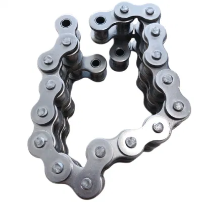
Can a bush chain be used in high-load applications?
Yes, bush chains are commonly used in high-load applications due to their robust design and ability to handle heavy loads. The construction of a bush chain allows it to transmit significant amounts of force and torque, making it suitable for demanding industrial applications.
Bush chains are designed with solid bushings and precision rollers that provide excellent load-carrying capacity. The bushings act as a bearing surface between the pins and the rollers, reducing friction and allowing for smooth rotation under high loads.
Furthermore, bush chains are available in various sizes and configurations to accommodate different load requirements. They are made from durable materials such as alloy steel or stainless steel, which further enhances their strength and load-bearing capabilities.
When selecting a bush chain for a high-load application, it is important to consider factors such as the anticipated load magnitude, operating conditions, and the desired safety margin. Proper lubrication and regular maintenance are also essential to ensure optimal performance and extend the service life of the bush chain in high-load applications.
Overall, bush chains are a reliable choice for transmitting high loads and are widely used in industries such as mining, construction, heavy machinery, and material handling.
editor by CX 2023-10-07
China Best Sales Chain Supply 04 B Series Short Pitch Precision Engineering and Construction Machinery Carbon Steel Simplex Timing Roller Chains and Bush Chains with Link
Product Description
B Series Short pitch Precision Simplex Roller Chains & Bush Chains
| ISO/DIN Chain No. |
Pitch
P |
Roller diameter
d1max |
Width between inner plates b1min mm |
Pin diameter
d2max |
Pin length | Inner plate depth h2max mm |
Plate thickness
t/Tmax |
Tensile strength
Qmin |
Average tensile strength Q0 kN |
Weight per meter q kg/m |
|
| Lmax mm |
Lcmax mm |
||||||||||
| 04 | 6.000 | 4.00 | 2.80 | 1.85 | 6.80 | 7.8 | 5.00 | 0.60 | 3.0/682 | 3.2 | 0.11 |
*Straight side plates
ROLLER CHAIN
Roller chain or bush roller chain is the type of chain drive most commonly used for transmission of mechanical power on many kinds of domestic, industrial and agricultural machinery, including conveyors, wire- and tube-drawing machines, printing presses, cars, motorcycles, and bicycles. It consists of a series of short cylindrical rollers held together by side links. It is driven by a toothed wheel called a sprocket. It is a simple, reliable, and efficient means of power transmission.
CONSTRUCTION OF THE CHAIN
Two different sizes of roller chain, showing construction.
There are 2 types of links alternating in the bush roller chain. The first type is inner links, having 2 inner plates held together by 2 sleeves or bushings CZPT which rotate 2 rollers. Inner links alternate with the second type, the outer links, consisting of 2 outer plates held together by pins passing through the bushings of the inner links. The “bushingless” roller chain is similar in operation though not in construction; instead of separate bushings or sleeves holding the inner plates together, the plate has a tube stamped into it protruding from the hole which serves the same purpose. This has the advantage of removing 1 step in assembly of the chain.
The roller chain design reduces friction compared to simpler designs, resulting in higher efficiency and less wear. The original power transmission chain varieties lacked rollers and bushings, with both the inner and outer plates held by pins which directly contacted the sprocket teeth; however this configuration exhibited extremely rapid wear of both the sprocket teeth, and the plates where they pivoted on the pins. This problem was partially solved by the development of bushed chains, with the pins holding the outer plates passing through bushings or sleeves connecting the inner plates. This distributed the wear over a greater area; however the teeth of the sprockets still wore more rapidly than is desirable, from the sliding friction against the bushings. The addition of rollers surrounding the bushing sleeves of the chain and provided rolling contact with the teeth of the sprockets resulting in excellent resistance to wear of both sprockets and chain as well. There is even very low friction, as long as the chain is sufficiently lubricated. Continuous, clean, lubrication of roller chains is of primary importance for efficient operation as well as correct tensioning.
LUBRICATION
Many driving chains (for example, in factory equipment, or driving a camshaft inside an internal combustion engine) operate in clean environments, and thus the wearing surfaces (that is, the pins and bushings) are safe from precipitation and airborne grit, many even in a sealed environment such as an oil bath. Some roller chains are designed to have o-rings built into the space between the outside link plate and the inside roller link plates. Chain manufacturers began to include this feature in 1971 after the application was invented by Joseph Montano while working for Whitney Chain of Hartford, Connecticut. O-rings were included as a way to improve lubrication to the links of power transmission chains, a service that is vitally important to extending their working life. These rubber fixtures form a barrier that holds factory applied lubricating grease inside the pin and bushing wear areas. Further, the rubber o-rings prevent dirt and other contaminants from entering inside the chain linkages, where such particles would otherwise cause significant wear.[citation needed]
There are also many chains that have to operate in dirty conditions, and for size or operational reasons cannot be sealed. Examples include chains on farm equipment, bicycles, and chain saws. These chains will necessarily have relatively high rates of wear, particularly when the operators are prepared to accept more friction, less efficiency, more noise and more frequent replacement as they neglect lubrication and adjustment.
Many oil-based lubricants attract dirt and other particles, eventually forming an CZPT paste that will compound wear on chains. This problem can be circumvented by use of a “dry” PTFE spray, which forms a solid film after application and repels both particles and moisture.
VARIANTS DESIGN
Layout of a roller chain: 1. Outer plate, 2. Inner plate, 3. Pin, 4. Bushing, 5. Roller
If the chain is not being used for a high wear application (for instance if it is just transmitting motion from a hand-operated lever to a control shaft on a machine, or a sliding door on an oven), then 1 of the simpler types of chain may still be used. Conversely, where extra strength but the smooth drive of a smaller pitch is required, the chain may be “siamesed”; instead of just 2 rows of plates on the outer sides of the chain, there may be 3 (“duplex”), 4 (“triplex”), or more rows of plates running parallel, with bushings and rollers between each adjacent pair, and the same number of rows of teeth running in parallel on the sprockets to match. Timing chains on automotive engines, for example, typically have multiple rows of plates called strands.
Roller chain is made in several sizes, the most common American National Standards Institute (ANSI) standards being 40, 50, 60, and 80. The first digit(s) indicate the pitch of the chain in eighths of an inch, with the last digit being 0 for standard chain, 1 for lightweight chain, and 5 for bushed chain with no rollers. Thus, a chain with half-inch pitch would be a #40 while a #160 sprocket would have teeth spaced 2 inches apart, etc. Metric pitches are expressed in sixteenths of an inch; thus a metric #8 chain (08B-1) would be equivalent to an ANSI #40. Most roller chain is made from plain carbon or alloy steel, but stainless steel is used in food processing machinery or other places where lubrication is a problem, and nylon or brass are occasionally seen for the same reason.
Roller chain is ordinarily hooked up using a master link (also known as a connecting link), which typically has 1 pin held by a horseshoe clip rather than friction fit, allowing it to be inserted or removed with simple tools. Chain with a removable link or pin is also known as cottered chain, which allows the length of the chain to be adjusted. Half links (also known as offsets) are available and are used to increase the length of the chain by a single roller. Riveted roller chain has the master link (also known as a connecting link) “riveted” or mashed on the ends. These pins are made to be durable and are not removable.
USE
An example of 2 ‘ghost’ sprockets tensioning a triplex roller chain system
Roller chains are used in low- to mid-speed drives at around 600 to 800 feet per minute; however, at higher speeds, around 2,000 to 3,000 feet per minute, V-belts are normally used due to wear and noise issues.
A bicycle chain is a form of roller chain. Bicycle chains may have a master link, or may require a chain tool for removal and installation. A similar but larger and thus stronger chain is used on most motorcycles although it is sometimes replaced by either a toothed belt or a shaft drive, which offer lower noise level and fewer maintenance requirements.
The great majority of automobile engines use roller chains to drive the camshaft(s). Very high performance engines often use gear drive, and starting in the early 1960s toothed belts were used by some manufacturers.
Chains are also used in forklifts using hydraulic rams as a pulley to raise and lower the carriage; however, these chains are not considered roller chains, but are classified as lift or leaf chains.
Chainsaw cutting chains superficially resemble roller chains but are more closely related to leaf chains. They are driven by projecting drive links which also serve to locate the chain CZPT the bar.
Sea Harrier FA.2 ZA195 front (cold) vector thrust nozzle – the nozzle is rotated by a chain drive from an air motor
A perhaps unusual use of a pair of motorcycle chains is in the Harrier Jump Jet, where a chain drive from an air motor is used to rotate the movable engine nozzles, allowing them to be pointed downwards for hovering flight, or to the rear for normal CZPT flight, a system known as Thrust vectoring.
WEAR
The effect of wear on a roller chain is to increase the pitch (spacing of the links), causing the chain to grow longer. Note that this is due to wear at the pivoting pins and bushes, not from actual stretching of the metal (as does happen to some flexible steel components such as the hand-brake cable of a motor vehicle).
With modern chains it is unusual for a chain (other than that of a bicycle) to wear until it breaks, since a worn chain leads to the rapid onset of wear on the teeth of the sprockets, with ultimate failure being the loss of all the teeth on the sprocket. The sprockets (in particular the smaller of the two) suffer a grinding motion that puts a characteristic hook shape into the driven face of the teeth. (This effect is made worse by a chain improperly tensioned, but is unavoidable no matter what care is taken). The worn teeth (and chain) no longer provides smooth transmission of power and this may become evident from the noise, the vibration or (in car engines using a timing chain) the variation in ignition timing seen with a timing light. Both sprockets and chain should be replaced in these cases, since a new chain on worn sprockets will not last long. However, in less severe cases it may be possible to save the larger of the 2 sprockets, since it is always the smaller 1 that suffers the most wear. Only in very light-weight applications such as a bicycle, or in extreme cases of improper tension, will the chain normally jump off the sprockets.
The lengthening due to wear of a chain is calculated by the following formula:
M = the length of a number of links measured
S = the number of links measured
P = Pitch
In industry, it is usual to monitor the movement of the chain tensioner (whether manual or automatic) or the exact length of a drive chain (one rule of thumb is to replace a roller chain which has elongated 3% on an adjustable drive or 1.5% on a fixed-center drive). A simpler method, particularly suitable for the cycle or motorcycle user, is to attempt to pull the chain away from the larger of the 2 sprockets, whilst ensuring the chain is taut. Any significant movement (e.g. making it possible to see through a gap) probably indicates a chain worn up to and beyond the limit. Sprocket damage will result if the problem is ignored. Sprocket wear cancels this effect, and may mask chain wear.
CHAIN STRENGTH
The most common measure of roller chain’s strength is tensile strength. Tensile strength represents how much load a chain can withstand under a one-time load before breaking. Just as important as tensile strength is a chain’s fatigue strength. The critical factors in a chain’s fatigue strength is the quality of steel used to manufacture the chain, the heat treatment of the chain components, the quality of the pitch hole fabrication of the linkplates, and the type of shot plus the intensity of shot peen coverage on the linkplates. Other factors can include the thickness of the linkplates and the design (contour) of the linkplates. The rule of thumb for roller chain operating on a continuous drive is for the chain load to not exceed a mere 1/6 or 1/9 of the chain’s tensile strength, depending on the type of master links used (press-fit vs. slip-fit)[citation needed]. Roller chains operating on a continuous drive beyond these thresholds can and typically do fail prematurely via linkplate fatigue failure.
The standard minimum ultimate strength of the ANSI 29.1 steel chain is 12,500 x (pitch, in inches)2. X-ring and O-Ring chains greatly decrease wear by means of internal lubricants, increasing chain life. The internal lubrication is inserted by means of a vacuum when riveting the chain together.
CHAIN STHangZhouRDS
Standards organizations (such as ANSI and ISO) maintain standards for design, dimensions, and interchangeability of transmission chains. For example, the following Table shows data from ANSI standard B29.1-2011 (Precision Power Transmission Roller Chains, Attachments, and Sprockets) developed by the American Society of Mechanical Engineers (ASME). See the references[8][9][10] for additional information.
ASME/ANSI B29.1-2011 Roller Chain Standard SizesSizePitchMaximum Roller DiameterMinimum Ultimate Tensile StrengthMeasuring Load25
| ASME/ANSI B29.1-2011 Roller Chain Standard Sizes | ||||
| Size | Pitch | Maximum Roller Diameter | Minimum Ultimate Tensile Strength | Measuring Load |
|---|---|---|---|---|
| 25 | 0.250 in (6.35 mm) | 0.130 in (3.30 mm) | 780 lb (350 kg) | 18 lb (8.2 kg) |
| 35 | 0.375 in (9.53 mm) | 0.200 in (5.08 mm) | 1,760 lb (800 kg) | 18 lb (8.2 kg) |
| 41 | 0.500 in (12.70 mm) | 0.306 in (7.77 mm) | 1,500 lb (680 kg) | 18 lb (8.2 kg) |
| 40 | 0.500 in (12.70 mm) | 0.312 in (7.92 mm) | 3,125 lb (1,417 kg) | 31 lb (14 kg) |
| 50 | 0.625 in (15.88 mm) | 0.400 in (10.16 mm) | 4,880 lb (2,210 kg) | 49 lb (22 kg) |
| 60 | 0.750 in (19.05 mm) | 0.469 in (11.91 mm) | 7,030 lb (3,190 kg) | 70 lb (32 kg) |
| 80 | 1.000 in (25.40 mm) | 0.625 in (15.88 mm) | 12,500 lb (5,700 kg) | 125 lb (57 kg) |
| 100 | 1.250 in (31.75 mm) | 0.750 in (19.05 mm) | 19,531 lb (8,859 kg) | 195 lb (88 kg) |
| 120 | 1.500 in (38.10 mm) | 0.875 in (22.23 mm) | 28,125 lb (12,757 kg) | 281 lb (127 kg) |
| 140 | 1.750 in (44.45 mm) | 1.000 in (25.40 mm) | 38,280 lb (17,360 kg) | 383 lb (174 kg) |
| 160 | 2.000 in (50.80 mm) | 1.125 in (28.58 mm) | 50,000 lb (23,000 kg) | 500 lb (230 kg) |
| 180 | 2.250 in (57.15 mm) | 1.460 in (37.08 mm) | 63,280 lb (28,700 kg) | 633 lb (287 kg) |
| 200 | 2.500 in (63.50 mm) | 1.562 in (39.67 mm) | 78,175 lb (35,460 kg) | 781 lb (354 kg) |
| 240 | 3.000 in (76.20 mm) | 1.875 in (47.63 mm) | 112,500 lb (51,000 kg) | 1,000 lb (450 kg |
For mnemonic purposes, below is another presentation of key dimensions from the same standard, expressed in fractions of an inch (which was part of the thinking behind the choice of preferred numbers in the ANSI standard):
| Pitch (inches) | Pitch expressed in eighths |
ANSI standard chain number |
Width (inches) |
|---|---|---|---|
| 1⁄4 | 2⁄8 | 25 | 1⁄8 |
| 3⁄8 | 3⁄8 | 35 | 3⁄16 |
| 1⁄2 | 4⁄8 | 41 | 1⁄4 |
| 1⁄2 | 4⁄8 | 40 | 5⁄16 |
| 5⁄8 | 5⁄8 | 50 | 3⁄8 |
| 3⁄4 | 6⁄8 | 60 | 1⁄2 |
| 1 | 8⁄8 | 80 | 5⁄8 |
Notes:
1. The pitch is the distance between roller centers. The width is the distance between the link plates (i.e. slightly more than the roller width to allow for clearance).
2. The right-hand digit of the standard denotes 0 = normal chain, 1 = lightweight chain, 5 = rollerless bushing chain.
3. The left-hand digit denotes the number of eighths of an inch that make up the pitch.
4. An “H” following the standard number denotes heavyweight chain. A hyphenated number following the standard number denotes double-strand (2), triple-strand (3), and so on. Thus 60H-3 denotes number 60 heavyweight triple-strand chain.
A typical bicycle chain (for derailleur gears) uses narrow 1⁄2-inch-pitch chain. The width of the chain is variable, and does not affect the load capacity. The more sprockets at the rear wheel (historically 3-6, nowadays 7-12 sprockets), the narrower the chain. Chains are sold according to the number of speeds they are designed to work with, for example, “10 speed chain”. Hub gear or single speed bicycles use 1/2″ x 1/8″ chains, where 1/8″ refers to the maximum thickness of a sprocket that can be used with the chain.
Typically chains with parallel shaped links have an even number of links, with each narrow link followed by a broad one. Chains built up with a uniform type of link, narrow at 1 and broad at the other end, can be made with an odd number of links, which can be an advantage to adapt to a special chainwheel-distance; on the other side such a chain tends to be not so strong.
Roller chains made using ISO standard are sometimes called as isochains.
WHY CHOOSE US
1. Reliable Quality Assurance System
2. Cutting-Edge Computer-Controlled CNC Machines
3. Bespoke Solutions from Highly Experienced Specialists
4. Customization and OEM Available for Specific Application
5. Extensive Inventory of Spare Parts and Accessories
6. Well-Developed CZPT Marketing Network
7. Efficient After-Sale Service System
The 219 sets of advanced automatic production equipment provide guarantees for high product quality. The 167 engineers and technicians with senior professional titles can design and develop products to meet the exact demands of customers, and OEM customizations are also available with us. Our sound global service network can provide customers with timely after-sales technical services.
We are not just a manufacturer and supplier, but also an industry consultant. We work pro-actively with you to offer expert advice and product recommendations in order to end up with a most cost effective product available for your specific application. The clients we serve CZPT range from end users to distributors and OEMs. Our OEM replacements can be substituted wherever necessary and suitable for both repair and new assemblies.
| Standard or Nonstandard: | Standard |
|---|---|
| Application: | Textile Machinery, Garment Machinery, Conveyer Equipment, Packaging Machinery, Electric Cars, Motorcycle, Food Machinery, Marine, Mining Equipment, Agricultural Machinery, Car, Food and Beverage Industry, Motorcycle Parts |
| Surface Treatment: | Polishing |
| Structure: | Roller Chain |
| Material: | Alloy |
| Type: | Short Pitch Chain |
| Samples: |
US$ 0/Meter
1 Meter(Min.Order) | |
|---|
| Customization: |
Available
| Customized Request |
|---|
How do you calculate the required length of a bush chain?
The length of a bush chain is determined by the distance between the sprockets or pulleys it needs to span. To calculate the required length, you can follow these steps:
1. Measure the distance between the centers of the sprockets or pulleys where the bush chain will be installed. This is known as the “center distance.”
2. Determine the number of chain links required. The number of links depends on the pitch of the bush chain, which is the distance between adjacent pins. The pitch is typically specified by the chain manufacturer.
3. Divide the center distance by the pitch of the chain to calculate the number of chain links needed. Round up to the nearest whole number to ensure proper engagement of the chain with the sprockets.
4. Multiply the number of chain links by the pitch to obtain the actual length of the chain required.
Keep in mind that the calculated chain length is a starting point and may need to be adjusted during installation. It is recommended to provide some additional slack in the chain to accommodate any tensioning or adjustment requirements.
It’s important to refer to the manufacturer’s specifications and guidelines for the specific bush chain you are using, as different chain types and designs may have variations in calculating the required length.
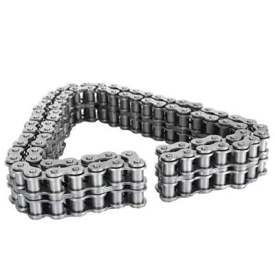
Can a bush chain be retrofitted into an existing system?
Yes, a bush chain can be retrofitted into an existing system in many cases. Retrofits are common when there is a need to upgrade or replace the existing chain with a more efficient or higher-quality option. The process of retrofitting a bush chain typically involves the following steps:
1. Evaluation of the existing system: The first step is to assess the existing system and determine if a bush chain can be installed. Factors such as space availability, compatibility with existing components, and load requirements need to be considered.
2. Selection of the appropriate bush chain: Once the system has been evaluated, the next step is to select the appropriate bush chain for the retrofit. This involves considering factors such as pitch, size, strength, and material compatibility to ensure a proper fit and optimal performance.
3. Modification of the system: Depending on the design of the existing system, some modifications may be required to accommodate the bush chain. This could involve adjusting the sprockets, modifying the chain guides, or making other necessary changes to ensure proper alignment and tensioning.
4. Installation of the bush chain: Once the modifications have been made, the bush chain can be installed into the existing system. This typically involves removing the old chain and replacing it with the new bush chain. Proper tensioning and alignment should be ensured during the installation process.
5. Testing and adjustments: After the bush chain is installed, it is important to conduct thorough testing to ensure proper operation. This includes checking for smooth movement, correct tension, and proper engagement with the sprockets. Any necessary adjustments should be made to optimize performance.
It is important to note that the feasibility of retrofitting a bush chain into an existing system depends on the specific requirements and design of the system. In some cases, additional modifications or adaptations may be needed to ensure compatibility and performance. Consulting with a qualified engineer or chain manufacturer can help determine the best approach for retrofitting a bush chain into an existing system.
How do you select the right bush chain for your application?
Choosing the right bush chain for your application is essential to ensure optimal performance and longevity. Here are some factors to consider when selecting a bush chain:
1. Load Capacity: Evaluate the maximum load that the chain will need to transmit. Consider factors such as weight, acceleration, and shock loads. Choose a bush chain with a load capacity that exceeds the anticipated load to ensure reliable operation.
2. Speed: Determine the operating speed of the chain. Higher speeds may require chains with specialized designs to minimize wear, reduce friction, and maintain accurate timing.
3. Environmental Conditions: Assess the environmental conditions in which the chain will operate. Consider factors such as temperature, humidity, dust, chemicals, and exposure to corrosive substances. Select a bush chain that is designed to withstand the specific conditions of your application.
4. Size and Configuration: Determine the required chain size based on the available space and the dimensions of the sprockets or pulleys. Consider the pitch, width, and overall dimensions of the chain. Additionally, assess whether a standard or custom configuration is needed to meet the application requirements.
5. Lubrication Requirements: Determine the lubrication method and frequency required for the chain. Some bush chains are self-lubricating, while others may require regular lubrication. Consider the availability of lubrication systems and the maintenance requirements of the chain.
6. Reliability and Durability: Assess the expected operational lifespan and the reliability requirements of your application. Look for bush chains from reputable manufacturers known for producing high-quality, durable products. Consider factors such as wear resistance, fatigue strength, and overall reliability.
7. Cost: Evaluate the cost-effectiveness of the bush chain, considering both the initial investment and long-term maintenance costs. Balance the performance requirements with the available budget.
Consult with a knowledgeable supplier or engineer to ensure you select the right bush chain that meets your specific application requirements. They can provide guidance based on their expertise and help you choose a chain that offers optimal performance and durability.
editor by CX 2023-09-08
China Standard Chain Supply 04 B Series Short Pitch Precision Engineering and Construction Machinery Carbon Steel Simplex Timing Roller Chains and Bush Chains with Link
Product Description
B Series Short pitch Precision Simplex Roller Chains & Bush Chains
| ISO/DIN Chain No. |
Pitch
P |
Roller diameter
d1max |
Width between inner plates b1min mm |
Pin diameter
d2max |
Pin length | Inner plate depth h2max mm |
Plate thickness
t/Tmax |
Tensile strength
Qmin |
Average tensile strength Q0 kN |
Weight per meter q kg/m |
|
| Lmax mm |
Lcmax mm |
||||||||||
| 04 | 6.000 | 4.00 | 2.80 | 1.85 | 6.80 | 7.8 | 5.00 | 0.60 | 3.0/682 | 3.2 | 0.11 |
*Straight side plates
ROLLER CHAIN
Roller chain or bush roller chain is the type of chain drive most commonly used for transmission of mechanical power on many kinds of domestic, industrial and agricultural machinery, including conveyors, wire- and tube-drawing machines, printing presses, cars, motorcycles, and bicycles. It consists of a series of short cylindrical rollers held together by side links. It is driven by a toothed wheel called a sprocket. It is a simple, reliable, and efficient means of power transmission.
CONSTRUCTION OF THE CHAIN
Two different sizes of roller chain, showing construction.
There are 2 types of links alternating in the bush roller chain. The first type is inner links, having 2 inner plates held together by 2 sleeves or bushings CZPT which rotate 2 rollers. Inner links alternate with the second type, the outer links, consisting of 2 outer plates held together by pins passing through the bushings of the inner links. The “bushingless” roller chain is similar in operation though not in construction; instead of separate bushings or sleeves holding the inner plates together, the plate has a tube stamped into it protruding from the hole which serves the same purpose. This has the advantage of removing 1 step in assembly of the chain.
The roller chain design reduces friction compared to simpler designs, resulting in higher efficiency and less wear. The original power transmission chain varieties lacked rollers and bushings, with both the inner and outer plates held by pins which directly contacted the sprocket teeth; however this configuration exhibited extremely rapid wear of both the sprocket teeth, and the plates where they pivoted on the pins. This problem was partially solved by the development of bushed chains, with the pins holding the outer plates passing through bushings or sleeves connecting the inner plates. This distributed the wear over a greater area; however the teeth of the sprockets still wore more rapidly than is desirable, from the sliding friction against the bushings. The addition of rollers surrounding the bushing sleeves of the chain and provided rolling contact with the teeth of the sprockets resulting in excellent resistance to wear of both sprockets and chain as well. There is even very low friction, as long as the chain is sufficiently lubricated. Continuous, clean, lubrication of roller chains is of primary importance for efficient operation as well as correct tensioning.
LUBRICATION
Many driving chains (for example, in factory equipment, or driving a camshaft inside an internal combustion engine) operate in clean environments, and thus the wearing surfaces (that is, the pins and bushings) are safe from precipitation and airborne grit, many even in a sealed environment such as an oil bath. Some roller chains are designed to have o-rings built into the space between the outside link plate and the inside roller link plates. Chain manufacturers began to include this feature in 1971 after the application was invented by Joseph Montano while working for Whitney Chain of Hartford, Connecticut. O-rings were included as a way to improve lubrication to the links of power transmission chains, a service that is vitally important to extending their working life. These rubber fixtures form a barrier that holds factory applied lubricating grease inside the pin and bushing wear areas. Further, the rubber o-rings prevent dirt and other contaminants from entering inside the chain linkages, where such particles would otherwise cause significant wear.[citation needed]
There are also many chains that have to operate in dirty conditions, and for size or operational reasons cannot be sealed. Examples include chains on farm equipment, bicycles, and chain saws. These chains will necessarily have relatively high rates of wear, particularly when the operators are prepared to accept more friction, less efficiency, more noise and more frequent replacement as they neglect lubrication and adjustment.
Many oil-based lubricants attract dirt and other particles, eventually forming an CZPT paste that will compound wear on chains. This problem can be circumvented by use of a “dry” PTFE spray, which forms a solid film after application and repels both particles and moisture.
VARIANTS DESIGN
Layout of a roller chain: 1. Outer plate, 2. Inner plate, 3. Pin, 4. Bushing, 5. Roller
If the chain is not being used for a high wear application (for instance if it is just transmitting motion from a hand-operated lever to a control shaft on a machine, or a sliding door on an oven), then 1 of the simpler types of chain may still be used. Conversely, where extra strength but the smooth drive of a smaller pitch is required, the chain may be “siamesed”; instead of just 2 rows of plates on the outer sides of the chain, there may be 3 (“duplex”), 4 (“triplex”), or more rows of plates running parallel, with bushings and rollers between each adjacent pair, and the same number of rows of teeth running in parallel on the sprockets to match. Timing chains on automotive engines, for example, typically have multiple rows of plates called strands.
Roller chain is made in several sizes, the most common American National Standards Institute (ANSI) standards being 40, 50, 60, and 80. The first digit(s) indicate the pitch of the chain in eighths of an inch, with the last digit being 0 for standard chain, 1 for lightweight chain, and 5 for bushed chain with no rollers. Thus, a chain with half-inch pitch would be a #40 while a #160 sprocket would have teeth spaced 2 inches apart, etc. Metric pitches are expressed in sixteenths of an inch; thus a metric #8 chain (08B-1) would be equivalent to an ANSI #40. Most roller chain is made from plain carbon or alloy steel, but stainless steel is used in food processing machinery or other places where lubrication is a problem, and nylon or brass are occasionally seen for the same reason.
Roller chain is ordinarily hooked up using a master link (also known as a connecting link), which typically has 1 pin held by a horseshoe clip rather than friction fit, allowing it to be inserted or removed with simple tools. Chain with a removable link or pin is also known as cottered chain, which allows the length of the chain to be adjusted. Half links (also known as offsets) are available and are used to increase the length of the chain by a single roller. Riveted roller chain has the master link (also known as a connecting link) “riveted” or mashed on the ends. These pins are made to be durable and are not removable.
USE
An example of 2 ‘ghost’ sprockets tensioning a triplex roller chain system
Roller chains are used in low- to mid-speed drives at around 600 to 800 feet per minute; however, at higher speeds, around 2,000 to 3,000 feet per minute, V-belts are normally used due to wear and noise issues.
A bicycle chain is a form of roller chain. Bicycle chains may have a master link, or may require a chain tool for removal and installation. A similar but larger and thus stronger chain is used on most motorcycles although it is sometimes replaced by either a toothed belt or a shaft drive, which offer lower noise level and fewer maintenance requirements.
The great majority of automobile engines use roller chains to drive the camshaft(s). Very high performance engines often use gear drive, and starting in the early 1960s toothed belts were used by some manufacturers.
Chains are also used in forklifts using hydraulic rams as a pulley to raise and lower the carriage; however, these chains are not considered roller chains, but are classified as lift or leaf chains.
Chainsaw cutting chains superficially resemble roller chains but are more closely related to leaf chains. They are driven by projecting drive links which also serve to locate the chain CZPT the bar.
Sea Harrier FA.2 ZA195 front (cold) vector thrust nozzle – the nozzle is rotated by a chain drive from an air motor
A perhaps unusual use of a pair of motorcycle chains is in the Harrier Jump Jet, where a chain drive from an air motor is used to rotate the movable engine nozzles, allowing them to be pointed downwards for hovering flight, or to the rear for normal CZPT flight, a system known as Thrust vectoring.
WEAR
The effect of wear on a roller chain is to increase the pitch (spacing of the links), causing the chain to grow longer. Note that this is due to wear at the pivoting pins and bushes, not from actual stretching of the metal (as does happen to some flexible steel components such as the hand-brake cable of a motor vehicle).
With modern chains it is unusual for a chain (other than that of a bicycle) to wear until it breaks, since a worn chain leads to the rapid onset of wear on the teeth of the sprockets, with ultimate failure being the loss of all the teeth on the sprocket. The sprockets (in particular the smaller of the two) suffer a grinding motion that puts a characteristic hook shape into the driven face of the teeth. (This effect is made worse by a chain improperly tensioned, but is unavoidable no matter what care is taken). The worn teeth (and chain) no longer provides smooth transmission of power and this may become evident from the noise, the vibration or (in car engines using a timing chain) the variation in ignition timing seen with a timing light. Both sprockets and chain should be replaced in these cases, since a new chain on worn sprockets will not last long. However, in less severe cases it may be possible to save the larger of the 2 sprockets, since it is always the smaller 1 that suffers the most wear. Only in very light-weight applications such as a bicycle, or in extreme cases of improper tension, will the chain normally jump off the sprockets.
The lengthening due to wear of a chain is calculated by the following formula:
M = the length of a number of links measured
S = the number of links measured
P = Pitch
In industry, it is usual to monitor the movement of the chain tensioner (whether manual or automatic) or the exact length of a drive chain (one rule of thumb is to replace a roller chain which has elongated 3% on an adjustable drive or 1.5% on a fixed-center drive). A simpler method, particularly suitable for the cycle or motorcycle user, is to attempt to pull the chain away from the larger of the 2 sprockets, whilst ensuring the chain is taut. Any significant movement (e.g. making it possible to see through a gap) probably indicates a chain worn up to and beyond the limit. Sprocket damage will result if the problem is ignored. Sprocket wear cancels this effect, and may mask chain wear.
CHAIN STRENGTH
The most common measure of roller chain’s strength is tensile strength. Tensile strength represents how much load a chain can withstand under a one-time load before breaking. Just as important as tensile strength is a chain’s fatigue strength. The critical factors in a chain’s fatigue strength is the quality of steel used to manufacture the chain, the heat treatment of the chain components, the quality of the pitch hole fabrication of the linkplates, and the type of shot plus the intensity of shot peen coverage on the linkplates. Other factors can include the thickness of the linkplates and the design (contour) of the linkplates. The rule of thumb for roller chain operating on a continuous drive is for the chain load to not exceed a mere 1/6 or 1/9 of the chain’s tensile strength, depending on the type of master links used (press-fit vs. slip-fit)[citation needed]. Roller chains operating on a continuous drive beyond these thresholds can and typically do fail prematurely via linkplate fatigue failure.
The standard minimum ultimate strength of the ANSI 29.1 steel chain is 12,500 x (pitch, in inches)2. X-ring and O-Ring chains greatly decrease wear by means of internal lubricants, increasing chain life. The internal lubrication is inserted by means of a vacuum when riveting the chain together.
CHAIN STHangZhouRDS
Standards organizations (such as ANSI and ISO) maintain standards for design, dimensions, and interchangeability of transmission chains. For example, the following Table shows data from ANSI standard B29.1-2011 (Precision Power Transmission Roller Chains, Attachments, and Sprockets) developed by the American Society of Mechanical Engineers (ASME). See the references[8][9][10] for additional information.
ASME/ANSI B29.1-2011 Roller Chain Standard SizesSizePitchMaximum Roller DiameterMinimum Ultimate Tensile StrengthMeasuring Load25
| ASME/ANSI B29.1-2011 Roller Chain Standard Sizes | ||||
| Size | Pitch | Maximum Roller Diameter | Minimum Ultimate Tensile Strength | Measuring Load |
|---|---|---|---|---|
| 25 | 0.250 in (6.35 mm) | 0.130 in (3.30 mm) | 780 lb (350 kg) | 18 lb (8.2 kg) |
| 35 | 0.375 in (9.53 mm) | 0.200 in (5.08 mm) | 1,760 lb (800 kg) | 18 lb (8.2 kg) |
| 41 | 0.500 in (12.70 mm) | 0.306 in (7.77 mm) | 1,500 lb (680 kg) | 18 lb (8.2 kg) |
| 40 | 0.500 in (12.70 mm) | 0.312 in (7.92 mm) | 3,125 lb (1,417 kg) | 31 lb (14 kg) |
| 50 | 0.625 in (15.88 mm) | 0.400 in (10.16 mm) | 4,880 lb (2,210 kg) | 49 lb (22 kg) |
| 60 | 0.750 in (19.05 mm) | 0.469 in (11.91 mm) | 7,030 lb (3,190 kg) | 70 lb (32 kg) |
| 80 | 1.000 in (25.40 mm) | 0.625 in (15.88 mm) | 12,500 lb (5,700 kg) | 125 lb (57 kg) |
| 100 | 1.250 in (31.75 mm) | 0.750 in (19.05 mm) | 19,531 lb (8,859 kg) | 195 lb (88 kg) |
| 120 | 1.500 in (38.10 mm) | 0.875 in (22.23 mm) | 28,125 lb (12,757 kg) | 281 lb (127 kg) |
| 140 | 1.750 in (44.45 mm) | 1.000 in (25.40 mm) | 38,280 lb (17,360 kg) | 383 lb (174 kg) |
| 160 | 2.000 in (50.80 mm) | 1.125 in (28.58 mm) | 50,000 lb (23,000 kg) | 500 lb (230 kg) |
| 180 | 2.250 in (57.15 mm) | 1.460 in (37.08 mm) | 63,280 lb (28,700 kg) | 633 lb (287 kg) |
| 200 | 2.500 in (63.50 mm) | 1.562 in (39.67 mm) | 78,175 lb (35,460 kg) | 781 lb (354 kg) |
| 240 | 3.000 in (76.20 mm) | 1.875 in (47.63 mm) | 112,500 lb (51,000 kg) | 1,000 lb (450 kg |
For mnemonic purposes, below is another presentation of key dimensions from the same standard, expressed in fractions of an inch (which was part of the thinking behind the choice of preferred numbers in the ANSI standard):
| Pitch (inches) | Pitch expressed in eighths |
ANSI standard chain number |
Width (inches) |
|---|---|---|---|
| 1⁄4 | 2⁄8 | 25 | 1⁄8 |
| 3⁄8 | 3⁄8 | 35 | 3⁄16 |
| 1⁄2 | 4⁄8 | 41 | 1⁄4 |
| 1⁄2 | 4⁄8 | 40 | 5⁄16 |
| 5⁄8 | 5⁄8 | 50 | 3⁄8 |
| 3⁄4 | 6⁄8 | 60 | 1⁄2 |
| 1 | 8⁄8 | 80 | 5⁄8 |
Notes:
1. The pitch is the distance between roller centers. The width is the distance between the link plates (i.e. slightly more than the roller width to allow for clearance).
2. The right-hand digit of the standard denotes 0 = normal chain, 1 = lightweight chain, 5 = rollerless bushing chain.
3. The left-hand digit denotes the number of eighths of an inch that make up the pitch.
4. An “H” following the standard number denotes heavyweight chain. A hyphenated number following the standard number denotes double-strand (2), triple-strand (3), and so on. Thus 60H-3 denotes number 60 heavyweight triple-strand chain.
A typical bicycle chain (for derailleur gears) uses narrow 1⁄2-inch-pitch chain. The width of the chain is variable, and does not affect the load capacity. The more sprockets at the rear wheel (historically 3-6, nowadays 7-12 sprockets), the narrower the chain. Chains are sold according to the number of speeds they are designed to work with, for example, “10 speed chain”. Hub gear or single speed bicycles use 1/2″ x 1/8″ chains, where 1/8″ refers to the maximum thickness of a sprocket that can be used with the chain.
Typically chains with parallel shaped links have an even number of links, with each narrow link followed by a broad one. Chains built up with a uniform type of link, narrow at 1 and broad at the other end, can be made with an odd number of links, which can be an advantage to adapt to a special chainwheel-distance; on the other side such a chain tends to be not so strong.
Roller chains made using ISO standard are sometimes called as isochains.
WHY CHOOSE US
1. Reliable Quality Assurance System
2. Cutting-Edge Computer-Controlled CNC Machines
3. Bespoke Solutions from Highly Experienced Specialists
4. Customization and OEM Available for Specific Application
5. Extensive Inventory of Spare Parts and Accessories
6. Well-Developed CZPT Marketing Network
7. Efficient After-Sale Service System
The 219 sets of advanced automatic production equipment provide guarantees for high product quality. The 167 engineers and technicians with senior professional titles can design and develop products to meet the exact demands of customers, and OEM customizations are also available with us. Our sound global service network can provide customers with timely after-sales technical services.
We are not just a manufacturer and supplier, but also an industry consultant. We work pro-actively with you to offer expert advice and product recommendations in order to end up with a most cost effective product available for your specific application. The clients we serve CZPT range from end users to distributors and OEMs. Our OEM replacements can be substituted wherever necessary and suitable for both repair and new assemblies.
| Standard or Nonstandard: | Standard |
|---|---|
| Application: | Textile Machinery, Garment Machinery, Conveyer Equipment, Packaging Machinery, Electric Cars, Motorcycle, Food Machinery, Marine, Mining Equipment, Agricultural Machinery, Car, Food and Beverage Industry, Motorcycle Parts |
| Surface Treatment: | Polishing |
| Structure: | Roller Chain |
| Material: | Alloy |
| Type: | Short Pitch Chain |
| Samples: |
US$ 0/Meter
1 Meter(Min.Order) | |
|---|
| Customization: |
Available
| Customized Request |
|---|
How does a bush chain handle reverse rotations and backdrives?
A bush chain is designed to handle reverse rotations and backdrives effectively. Here’s how it works:
1. Non-Slip Design: Bush chains are typically constructed with interlocking link plates and precision-fitted bushings. This design ensures that the chain maintains a positive engagement with the sprockets, preventing slippage or disengagement during reverse rotations or backdrives.
2. Tooth Profile: The sprockets used with bush chains are designed with a specific tooth profile that helps in maintaining proper chain engagement even during reverse rotations. The tooth shape ensures a smooth transition of the chain from one tooth to another, minimizing the risk of skipping or jumping off the sprocket.
3. Backstop Mechanisms: In some applications where backdrives or reverse rotations are more common, additional backstop mechanisms may be employed. These mechanisms prevent the chain from moving in the undesired direction by utilizing devices such as one-way clutches or backstop sprockets.
4. Proper Chain Tension: Maintaining proper chain tension is crucial for reliable operation in reverse rotations and backdrives. Adequate tension ensures that the chain remains engaged with the sprockets and minimizes the possibility of slippage.
Overall, bush chains are designed to handle reverse rotations and backdrives without compromising their performance and reliability. However, it is important to consider the specific application requirements and consult with chain manufacturers or experts to ensure the selection of the appropriate bush chain design and components for the desired operating conditions.
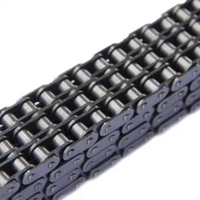
Can a bush chain be used in vertical lifting applications?
Yes, bush chains can be used in vertical lifting applications. The design and construction of bush chains make them suitable for transmitting power and lifting heavy loads in a vertical direction. Bush chains are commonly used in various vertical lifting systems such as elevators, cranes, hoists, and material handling equipment.
When utilizing a bush chain for vertical lifting, several factors should be considered:
1. Load capacity: Determine the maximum load that the bush chain needs to support during the lifting operation. Select a bush chain with an appropriate load capacity to ensure it can handle the weight of the load.
2. Safety factors: Consider the safety requirements and regulations for vertical lifting applications. Ensure that the selected bush chain meets the necessary safety standards and has a sufficient factor of safety to handle the intended load.
3. Speed and acceleration: Evaluate the desired lifting speed and acceleration. Take into account the weight of the load, the distance to be lifted, and the required lifting time. Ensure that the bush chain is capable of safely lifting the load at the desired speed and acceleration.
4. Tensioning and alignment: Proper tensioning and alignment are crucial for the smooth and reliable operation of a bush chain in vertical lifting applications. Ensure that the bush chain is properly tensioned and aligned to prevent issues such as chain slack, skipping, or jamming.
5. Lubrication: Provide adequate lubrication to reduce friction and wear between the bush chain components. Lubrication helps to prolong the life of the chain and ensures smooth movement during the lifting operation. Select the appropriate lubrication method based on the application requirements and operating conditions.
It is important to consult the manufacturer’s guidelines and specifications when selecting and installing a bush chain for vertical lifting applications. Proper maintenance and regular inspections should also be conducted to ensure the safe and reliable operation of the bush chain in the vertical lifting system.
What is a bush chain and how does it work?
A bush chain, also known as a bush roller chain or a bushing chain, is a type of roller chain commonly used in mechanical power transmission systems. It consists of a series of interconnected links, known as bushings, that are joined together by pins. The bushings are cylindrical metal sleeves with internal bearings that rotate on the pins.
The working principle of a bush chain is based on the interaction between the rotating bushings and the teeth of the sprockets. The chain is wrapped around two or more sprockets, with one sprocket being the driver and the other(s) being the driven. As the driver sprocket rotates, it pulls the chain, causing the bushings to rotate on the pins.
Each bushing has an outer surface that comes into contact with the sprocket teeth. The engagement between the sprocket teeth and the bushings’ outer surface creates the driving force, allowing power to be transmitted from the driver sprocket to the driven sprocket(s). This rotational motion transfers torque and enables the movement of various mechanical components or systems connected to the driven sprocket(s).
The bush chain design provides several advantages, including high tensile strength, flexibility, and the ability to transmit power over long distances. The bushings and pins are typically made of hardened steel to ensure durability and resistance to wear. Lubrication is essential to reduce friction and prevent premature wear of the bushings and pins.
Bush chains are widely used in various applications, such as industrial machinery, agricultural equipment, automotive systems, and conveyor systems. They are favored for their reliability, efficiency, and ease of installation. Proper maintenance, including regular lubrication and tension adjustment, is necessary to ensure the smooth operation and longevity of a bush chain.
editor by CX 2023-09-07
China Good quality Agricultural Conveyor 08b-1 B Series Short Pitch Precision Simplex Roller Chains and Bush Chains with Link
Product Description
B Series Short pitch Precision Simplex Roller Chains & Bush Chains
| ISO/DIN Chain No. |
Pitch
P |
Roller diameter
d1max |
Width between inner plates b1min mm |
Pin diameter
d2max |
Pin length | Inner plate depth h2max mm |
Plate thickness
t/Tmax |
Tensile strength
Qmin |
Average tensile strength Q0 kN |
Weight per meter q kg/m |
|
| Lmax mm |
Lcmax mm |
||||||||||
| 08B-1 | 12.700 | 8.51 | 7.75 | 4.45 | 16.70 | 18.2 | 11.80 | 1.60 | 18.0/4091 | 19.4 | 0.69 |
*Straight side plates
ROLLER CHAIN
Roller chain or bush roller chain is the type of chain drive most commonly used for transmission of mechanical power on many kinds of domestic, industrial and agricultural machinery, including conveyors, wire- and tube-drawing machines, printing presses, cars, motorcycles, and bicycles. It consists of a series of short cylindrical rollers held together by side links. It is driven by a toothed wheel called a sprocket. It is a simple, reliable, and efficient means of power transmission.
CONSTRUCTION OF THE CHAIN
Two different sizes of roller chain, showing construction.
There are 2 types of links alternating in the bush roller chain. The first type is inner links, having 2 inner plates held together by 2 sleeves or bushings CZPT which rotate 2 rollers. Inner links alternate with the second type, the outer links, consisting of 2 outer plates held together by pins passing through the bushings of the inner links. The “bushingless” roller chain is similar in operation though not in construction; instead of separate bushings or sleeves holding the inner plates together, the plate has a tube stamped into it protruding from the hole which serves the same purpose. This has the advantage of removing 1 step in assembly of the chain.
The roller chain design reduces friction compared to simpler designs, resulting in higher efficiency and less wear. The original power transmission chain varieties lacked rollers and bushings, with both the inner and outer plates held by pins which directly contacted the sprocket teeth; however this configuration exhibited extremely rapid wear of both the sprocket teeth, and the plates where they pivoted on the pins. This problem was partially solved by the development of bushed chains, with the pins holding the outer plates passing through bushings or sleeves connecting the inner plates. This distributed the wear over a greater area; however the teeth of the sprockets still wore more rapidly than is desirable, from the sliding friction against the bushings. The addition of rollers surrounding the bushing sleeves of the chain and provided rolling contact with the teeth of the sprockets resulting in excellent resistance to wear of both sprockets and chain as well. There is even very low friction, as long as the chain is sufficiently lubricated. Continuous, clean, lubrication of roller chains is of primary importance for efficient operation as well as correct tensioning.
LUBRICATION
Many driving chains (for example, in factory equipment, or driving a camshaft inside an internal combustion engine) operate in clean environments, and thus the wearing surfaces (that is, the pins and bushings) are safe from precipitation and airborne grit, many even in a sealed environment such as an oil bath. Some roller chains are designed to have o-rings built into the space between the outside link plate and the inside roller link plates. Chain manufacturers began to include this feature in 1971 after the application was invented by Joseph Montano while working for Whitney Chain of Hartford, Connecticut. O-rings were included as a way to improve lubrication to the links of power transmission chains, a service that is vitally important to extending their working life. These rubber fixtures form a barrier that holds factory applied lubricating grease inside the pin and bushing wear areas. Further, the rubber o-rings prevent dirt and other contaminants from entering inside the chain linkages, where such particles would otherwise cause significant wear.[citation needed]
There are also many chains that have to operate in dirty conditions, and for size or operational reasons cannot be sealed. Examples include chains on farm equipment, bicycles, and chain saws. These chains will necessarily have relatively high rates of wear, particularly when the operators are prepared to accept more friction, less efficiency, more noise and more frequent replacement as they neglect lubrication and adjustment.
Many oil-based lubricants attract dirt and other particles, eventually forming an CZPT paste that will compound wear on chains. This problem can be circumvented by use of a “dry” PTFE spray, which forms a solid film after application and repels both particles and moisture.
VARIANTS DESIGN
Layout of a roller chain: 1. Outer plate, 2. Inner plate, 3. Pin, 4. Bushing, 5. Roller
If the chain is not being used for a high wear application (for instance if it is just transmitting motion from a hand-operated lever to a control shaft on a machine, or a sliding door on an oven), then 1 of the simpler types of chain may still be used. Conversely, where extra strength but the smooth drive of a smaller pitch is required, the chain may be “siamesed”; instead of just 2 rows of plates on the outer sides of the chain, there may be 3 (“duplex”), 4 (“triplex”), or more rows of plates running parallel, with bushings and rollers between each adjacent pair, and the same number of rows of teeth running in parallel on the sprockets to match. Timing chains on automotive engines, for example, typically have multiple rows of plates called strands.
Roller chain is made in several sizes, the most common American National Standards Institute (ANSI) standards being 40, 50, 60, and 80. The first digit(s) indicate the pitch of the chain in eighths of an inch, with the last digit being 0 for standard chain, 1 for lightweight chain, and 5 for bushed chain with no rollers. Thus, a chain with half-inch pitch would be a #40 while a #160 sprocket would have teeth spaced 2 inches apart, etc. Metric pitches are expressed in sixteenths of an inch; thus a metric #8 chain (08B-1) would be equivalent to an ANSI #40. Most roller chain is made from plain carbon or alloy steel, but stainless steel is used in food processing machinery or other places where lubrication is a problem, and nylon or brass are occasionally seen for the same reason.
Roller chain is ordinarily hooked up using a master link (also known as a connecting link), which typically has 1 pin held by a horseshoe clip rather than friction fit, allowing it to be inserted or removed with simple tools. Chain with a removable link or pin is also known as cottered chain, which allows the length of the chain to be adjusted. Half links (also known as offsets) are available and are used to increase the length of the chain by a single roller. Riveted roller chain has the master link (also known as a connecting link) “riveted” or mashed on the ends. These pins are made to be durable and are not removable.
USE
An example of 2 ‘ghost’ sprockets tensioning a triplex roller chain system
Roller chains are used in low- to mid-speed drives at around 600 to 800 feet per minute; however, at higher speeds, around 2,000 to 3,000 feet per minute, V-belts are normally used due to wear and noise issues.
A bicycle chain is a form of roller chain. Bicycle chains may have a master link, or may require a chain tool for removal and installation. A similar but larger and thus stronger chain is used on most motorcycles although it is sometimes replaced by either a toothed belt or a shaft drive, which offer lower noise level and fewer maintenance requirements.
The great majority of automobile engines use roller chains to drive the camshaft(s). Very high performance engines often use gear drive, and starting in the early 1960s toothed belts were used by some manufacturers.
Chains are also used in forklifts using hydraulic rams as a pulley to raise and lower the carriage; however, these chains are not considered roller chains, but are classified as lift or leaf chains.
Chainsaw cutting chains superficially resemble roller chains but are more closely related to leaf chains. They are driven by projecting drive links which also serve to locate the chain CZPT the bar.
Sea Harrier FA.2 ZA195 front (cold) vector thrust nozzle – the nozzle is rotated by a chain drive from an air motor
A perhaps unusual use of a pair of motorcycle chains is in the Harrier Jump Jet, where a chain drive from an air motor is used to rotate the movable engine nozzles, allowing them to be pointed downwards for hovering flight, or to the rear for normal CZPT flight, a system known as Thrust vectoring.
WEAR
The effect of wear on a roller chain is to increase the pitch (spacing of the links), causing the chain to grow longer. Note that this is due to wear at the pivoting pins and bushes, not from actual stretching of the metal (as does happen to some flexible steel components such as the hand-brake cable of a motor vehicle).
With modern chains it is unusual for a chain (other than that of a bicycle) to wear until it breaks, since a worn chain leads to the rapid onset of wear on the teeth of the sprockets, with ultimate failure being the loss of all the teeth on the sprocket. The sprockets (in particular the smaller of the two) suffer a grinding motion that puts a characteristic hook shape into the driven face of the teeth. (This effect is made worse by a chain improperly tensioned, but is unavoidable no matter what care is taken). The worn teeth (and chain) no longer provides smooth transmission of power and this may become evident from the noise, the vibration or (in car engines using a timing chain) the variation in ignition timing seen with a timing light. Both sprockets and chain should be replaced in these cases, since a new chain on worn sprockets will not last long. However, in less severe cases it may be possible to save the larger of the 2 sprockets, since it is always the smaller 1 that suffers the most wear. Only in very light-weight applications such as a bicycle, or in extreme cases of improper tension, will the chain normally jump off the sprockets.
The lengthening due to wear of a chain is calculated by the following formula:
M = the length of a number of links measured
S = the number of links measured
P = Pitch
In industry, it is usual to monitor the movement of the chain tensioner (whether manual or automatic) or the exact length of a drive chain (one rule of thumb is to replace a roller chain which has elongated 3% on an adjustable drive or 1.5% on a fixed-center drive). A simpler method, particularly suitable for the cycle or motorcycle user, is to attempt to pull the chain away from the larger of the 2 sprockets, whilst ensuring the chain is taut. Any significant movement (e.g. making it possible to see through a gap) probably indicates a chain worn up to and beyond the limit. Sprocket damage will result if the problem is ignored. Sprocket wear cancels this effect, and may mask chain wear.
CHAIN STRENGTH
The most common measure of roller chain’s strength is tensile strength. Tensile strength represents how much load a chain can withstand under a one-time load before breaking. Just as important as tensile strength is a chain’s fatigue strength. The critical factors in a chain’s fatigue strength is the quality of steel used to manufacture the chain, the heat treatment of the chain components, the quality of the pitch hole fabrication of the linkplates, and the type of shot plus the intensity of shot peen coverage on the linkplates. Other factors can include the thickness of the linkplates and the design (contour) of the linkplates. The rule of thumb for roller chain operating on a continuous drive is for the chain load to not exceed a mere 1/6 or 1/9 of the chain’s tensile strength, depending on the type of master links used (press-fit vs. slip-fit)[citation needed]. Roller chains operating on a continuous drive beyond these thresholds can and typically do fail prematurely via linkplate fatigue failure.
The standard minimum ultimate strength of the ANSI 29.1 steel chain is 12,500 x (pitch, in inches)2. X-ring and O-Ring chains greatly decrease wear by means of internal lubricants, increasing chain life. The internal lubrication is inserted by means of a vacuum when riveting the chain together.
CHAIN STHangZhouRDS
Standards organizations (such as ANSI and ISO) maintain standards for design, dimensions, and interchangeability of transmission chains. For example, the following Table shows data from ANSI standard B29.1-2011 (Precision Power Transmission Roller Chains, Attachments, and Sprockets) developed by the American Society of Mechanical Engineers (ASME). See the references[8][9][10] for additional information.
ASME/ANSI B29.1-2011 Roller Chain Standard SizesSizePitchMaximum Roller DiameterMinimum Ultimate Tensile StrengthMeasuring Load25
| ASME/ANSI B29.1-2011 Roller Chain Standard Sizes | ||||
| Size | Pitch | Maximum Roller Diameter | Minimum Ultimate Tensile Strength | Measuring Load |
|---|---|---|---|---|
| 25 | 0.250 in (6.35 mm) | 0.130 in (3.30 mm) | 780 lb (350 kg) | 18 lb (8.2 kg) |
| 35 | 0.375 in (9.53 mm) | 0.200 in (5.08 mm) | 1,760 lb (800 kg) | 18 lb (8.2 kg) |
| 41 | 0.500 in (12.70 mm) | 0.306 in (7.77 mm) | 1,500 lb (680 kg) | 18 lb (8.2 kg) |
| 40 | 0.500 in (12.70 mm) | 0.312 in (7.92 mm) | 3,125 lb (1,417 kg) | 31 lb (14 kg) |
| 50 | 0.625 in (15.88 mm) | 0.400 in (10.16 mm) | 4,880 lb (2,210 kg) | 49 lb (22 kg) |
| 60 | 0.750 in (19.05 mm) | 0.469 in (11.91 mm) | 7,030 lb (3,190 kg) | 70 lb (32 kg) |
| 80 | 1.000 in (25.40 mm) | 0.625 in (15.88 mm) | 12,500 lb (5,700 kg) | 125 lb (57 kg) |
| 100 | 1.250 in (31.75 mm) | 0.750 in (19.05 mm) | 19,531 lb (8,859 kg) | 195 lb (88 kg) |
| 120 | 1.500 in (38.10 mm) | 0.875 in (22.23 mm) | 28,125 lb (12,757 kg) | 281 lb (127 kg) |
| 140 | 1.750 in (44.45 mm) | 1.000 in (25.40 mm) | 38,280 lb (17,360 kg) | 383 lb (174 kg) |
| 160 | 2.000 in (50.80 mm) | 1.125 in (28.58 mm) | 50,000 lb (23,000 kg) | 500 lb (230 kg) |
| 180 | 2.250 in (57.15 mm) | 1.460 in (37.08 mm) | 63,280 lb (28,700 kg) | 633 lb (287 kg) |
| 200 | 2.500 in (63.50 mm) | 1.562 in (39.67 mm) | 78,175 lb (35,460 kg) | 781 lb (354 kg) |
| 240 | 3.000 in (76.20 mm) | 1.875 in (47.63 mm) | 112,500 lb (51,000 kg) | 1,000 lb (450 kg |
For mnemonic purposes, below is another presentation of key dimensions from the same standard, expressed in fractions of an inch (which was part of the thinking behind the choice of preferred numbers in the ANSI standard):
| Pitch (inches) | Pitch expressed in eighths |
ANSI standard chain number |
Width (inches) |
|---|---|---|---|
| 1⁄4 | 2⁄8 | 25 | 1⁄8 |
| 3⁄8 | 3⁄8 | 35 | 3⁄16 |
| 1⁄2 | 4⁄8 | 41 | 1⁄4 |
| 1⁄2 | 4⁄8 | 40 | 5⁄16 |
| 5⁄8 | 5⁄8 | 50 | 3⁄8 |
| 3⁄4 | 6⁄8 | 60 | 1⁄2 |
| 1 | 8⁄8 | 80 | 5⁄8 |
Notes:
1. The pitch is the distance between roller centers. The width is the distance between the link plates (i.e. slightly more than the roller width to allow for clearance).
2. The right-hand digit of the standard denotes 0 = normal chain, 1 = lightweight chain, 5 = rollerless bushing chain.
3. The left-hand digit denotes the number of eighths of an inch that make up the pitch.
4. An “H” following the standard number denotes heavyweight chain. A hyphenated number following the standard number denotes double-strand (2), triple-strand (3), and so on. Thus 60H-3 denotes number 60 heavyweight triple-strand chain.
A typical bicycle chain (for derailleur gears) uses narrow 1⁄2-inch-pitch chain. The width of the chain is variable, and does not affect the load capacity. The more sprockets at the rear wheel (historically 3-6, nowadays 7-12 sprockets), the narrower the chain. Chains are sold according to the number of speeds they are designed to work with, for example, “10 speed chain”. Hub gear or single speed bicycles use 1/2″ x 1/8″ chains, where 1/8″ refers to the maximum thickness of a sprocket that can be used with the chain.
Typically chains with parallel shaped links have an even number of links, with each narrow link followed by a broad one. Chains built up with a uniform type of link, narrow at 1 and broad at the other end, can be made with an odd number of links, which can be an advantage to adapt to a special chainwheel-distance; on the other side such a chain tends to be not so strong.
Roller chains made using ISO standard are sometimes called as isochains.
WHY CHOOSE US
1. Reliable Quality Assurance System
2. Cutting-Edge Computer-Controlled CNC Machines
3. Bespoke Solutions from Highly Experienced Specialists
4. Customization and OEM Available for Specific Application
5. Extensive Inventory of Spare Parts and Accessories
6. Well-Developed CZPT Marketing Network
7. Efficient After-Sale Service System
The 219 sets of advanced automatic production equipment provide guarantees for high product quality. The 167 engineers and technicians with senior professional titles can design and develop products to meet the exact demands of customers, and OEM customizations are also available with us. Our sound global service network can provide customers with timely after-sales technical services.
We are not just a manufacturer and supplier, but also an industry consultant. We work pro-actively with you to offer expert advice and product recommendations in order to end up with a most cost effective product available for your specific application. The clients we serve CZPT range from end users to distributors and OEMs. Our OEM replacements can be substituted wherever necessary and suitable for both repair and new assemblies.
| Usage: | Transmission Chain, Drag Chain, Conveyor Chain, Dedicated Special Chain |
|---|---|
| Material: | Alloy |
| Surface Treatment: | Polishing |
| Feature: | Heat Resistant |
| Chain Size: | Roller Chains |
| Structure: | Roller Chain |
| Samples: |
US$ 0/Meter
1 Meter(Min.Order) | |
|---|
| Customization: |
Available
| Customized Request |
|---|
What are the maintenance requirements for a bush chain?
Maintaining a bush chain is essential to ensure its optimal performance and longevity. Here are the key maintenance requirements for a bush chain:
1. Regular cleaning: Regularly clean the bush chain to remove dirt, debris, and contaminants that can cause abrasion and accelerated wear. Use a brush or compressed air to clean the chain thoroughly.
2. Lubrication: Proper lubrication is crucial for the smooth operation and reduced friction of a bush chain. Apply the recommended lubricant to all the chain components, including the pins, bushings, and rollers. Follow the manufacturer’s guidelines for the appropriate lubricant type and frequency of lubrication.
3. Tension adjustment: Check the tension of the bush chain regularly and adjust it if necessary. Proper tension ensures optimal performance and reduces the risk of premature wear or failure. Consult the manufacturer’s guidelines or expert advice for the correct tensioning procedure specific to your chain.
4. Inspection: Conduct regular inspections of the bush chain to identify any signs of wear, damage, or misalignment. Inspect the chain for elongation, broken or damaged components, and misalignment. Replace any worn or damaged parts promptly to prevent further issues.
5. Replace worn components: Over time, the components of a bush chain, such as pins, bushings, and rollers, may wear out and require replacement. Monitor the wear levels of these components and replace them when they reach the manufacturer’s recommended limits.
6. Environmental considerations: Consider the operating environment of the bush chain and take appropriate measures to protect it. In corrosive or harsh environments, use corrosion-resistant chain materials or coatings to prevent accelerated wear.
7. Training and documentation: Ensure that maintenance personnel are properly trained in bush chain maintenance procedures. Keep detailed records of maintenance activities, including lubrication schedules, tension adjustments, and component replacements.
By following these maintenance requirements, you can extend the lifespan of your bush chain and maintain its optimal performance. Regular maintenance and timely replacement of worn components will help prevent unexpected failures and costly downtime.
Can a bush chain be used in corrosive or harsh environments?
Yes, a bush chain can be used in corrosive or harsh environments, but it requires careful selection and proper maintenance to ensure optimal performance and longevity. Here are some considerations:
1. Material Selection: When operating in corrosive environments, it is crucial to select a bush chain made from corrosion-resistant materials such as stainless steel or specialty alloys. These materials offer enhanced resistance to corrosion and chemical attack.
2. Coatings and Surface Treatments: Applying coatings or surface treatments to the bush chain can provide additional protection against corrosion. For example, coatings like zinc plating, nickel plating, or chemical treatments can help inhibit rust and corrosion.
3. Sealing and Protection: In harsh environments, it is essential to protect the bush chain from contaminants and corrosive substances. Enclosing the chain in a protective housing or using seals, covers, or boots can help prevent the entry of corrosive agents and debris.
4. Proper Lubrication: Adequate lubrication is crucial for reducing friction and preventing corrosion. Choose lubricants specifically designed for use in corrosive environments, such as those with anti-corrosion additives. Regular lubrication maintenance is necessary to ensure the chain remains well-lubricated and protected.
5. Cleaning and Maintenance: Regular cleaning and maintenance are vital to remove any corrosive substances or contaminants that may have accumulated on the chain. This includes thorough cleaning, inspection, and re-lubrication as necessary.
It is important to consult with chain manufacturers or industry experts to determine the most suitable bush chain and maintenance practices for the specific corrosive or harsh environment. By implementing these measures, a bush chain can effectively operate and withstand the challenges posed by corrosive or harsh conditions.
What is a bush chain and how does it work?
A bush chain, also known as a bush roller chain or a bushing chain, is a type of roller chain commonly used in mechanical power transmission systems. It consists of a series of interconnected links, known as bushings, that are joined together by pins. The bushings are cylindrical metal sleeves with internal bearings that rotate on the pins.
The working principle of a bush chain is based on the interaction between the rotating bushings and the teeth of the sprockets. The chain is wrapped around two or more sprockets, with one sprocket being the driver and the other(s) being the driven. As the driver sprocket rotates, it pulls the chain, causing the bushings to rotate on the pins.
Each bushing has an outer surface that comes into contact with the sprocket teeth. The engagement between the sprocket teeth and the bushings’ outer surface creates the driving force, allowing power to be transmitted from the driver sprocket to the driven sprocket(s). This rotational motion transfers torque and enables the movement of various mechanical components or systems connected to the driven sprocket(s).
The bush chain design provides several advantages, including high tensile strength, flexibility, and the ability to transmit power over long distances. The bushings and pins are typically made of hardened steel to ensure durability and resistance to wear. Lubrication is essential to reduce friction and prevent premature wear of the bushings and pins.
Bush chains are widely used in various applications, such as industrial machinery, agricultural equipment, automotive systems, and conveyor systems. They are favored for their reliability, efficiency, and ease of installation. Proper maintenance, including regular lubrication and tension adjustment, is necessary to ensure the smooth operation and longevity of a bush chain.
editor by CX 2023-08-21
China Custom Conveyor Belt 240h-2 Heavy Duty Series Duplex Roller Chains and Bush Chains with Link and Marine Hardware
Product Description
Heavy Duty Series Duplex Roller Chains & Bush Chains
| ISO/ANSI Chain No. |
Pitch
P |
Roller diameter
d1max |
Width between inner plates b1min mm |
Pin diameter
d2max |
Pin length | Inner plate depth h2max mm |
Plate thickness
Tmax |
Transverse pitch Pt mm |
Tensile strength
Qmin |
Average tensile strength Q0 kN |
Weight per meter q kg/m |
|
| Lmax mm |
Lcmax mm |
|||||||||||
| 240H-2 | 76.200 | 47.63 | 47.35 | 23.81 | 212.6 | 223.1 | 72.30 | 12.70 | 101.22 | 1000/227270 | 1200.0 | 60.50 |
ROLLER CHAIN
Roller chain or bush roller chain is the type of chain drive most commonly used for transmission of mechanical power on many kinds of domestic, industrial and agricultural machinery, including conveyors, wire- and tube-drawing machines, printing presses, cars, motorcycles, and bicycles. It consists of a series of short cylindrical rollers held together by side links. It is driven by a toothed wheel called a sprocket. It is a simple, reliable, and efficient means of power transmission.
CONSTRUCTION OF THE CHAIN
Two different sizes of roller chain, showing construction.
There are 2 types of links alternating in the bush roller chain. The first type is inner links, having 2 inner plates held together by 2 sleeves or bushings CZPT which rotate 2 rollers. Inner links alternate with the second type, the outer links, consisting of 2 outer plates held together by pins passing through the bushings of the inner links. The “bushingless” roller chain is similar in operation though not in construction; instead of separate bushings or sleeves holding the inner plates together, the plate has a tube stamped into it protruding from the hole which serves the same purpose. This has the advantage of removing 1 step in assembly of the chain.
The roller chain design reduces friction compared to simpler designs, resulting in higher efficiency and less wear. The original power transmission chain varieties lacked rollers and bushings, with both the inner and outer plates held by pins which directly contacted the sprocket teeth; however this configuration exhibited extremely rapid wear of both the sprocket teeth, and the plates where they pivoted on the pins. This problem was partially solved by the development of bushed chains, with the pins holding the outer plates passing through bushings or sleeves connecting the inner plates. This distributed the wear over a greater area; however the teeth of the sprockets still wore more rapidly than is desirable, from the sliding friction against the bushings. The addition of rollers surrounding the bushing sleeves of the chain and provided rolling contact with the teeth of the sprockets resulting in excellent resistance to wear of both sprockets and chain as well. There is even very low friction, as long as the chain is sufficiently lubricated. Continuous, clean, lubrication of roller chains is of primary importance for efficient operation as well as correct tensioning.
LUBRICATION
Many driving chains (for example, in factory equipment, or driving a camshaft inside an internal combustion engine) operate in clean environments, and thus the wearing surfaces (that is, the pins and bushings) are safe from precipitation and airborne grit, many even in a sealed environment such as an oil bath. Some roller chains are designed to have o-rings built into the space between the outside link plate and the inside roller link plates. Chain manufacturers began to include this feature in 1971 after the application was invented by Joseph Montano while working for Whitney Chain of Hartford, Connecticut. O-rings were included as a way to improve lubrication to the links of power transmission chains, a service that is vitally important to extending their working life. These rubber fixtures form a barrier that holds factory applied lubricating grease inside the pin and bushing wear areas. Further, the rubber o-rings prevent dirt and other contaminants from entering inside the chain linkages, where such particles would otherwise cause significant wear.[citation needed]
There are also many chains that have to operate in dirty conditions, and for size or operational reasons cannot be sealed. Examples include chains on farm equipment, bicycles, and chain saws. These chains will necessarily have relatively high rates of wear, particularly when the operators are prepared to accept more friction, less efficiency, more noise and more frequent replacement as they neglect lubrication and adjustment.
Many oil-based lubricants attract dirt and other particles, eventually forming an CZPT paste that will compound wear on chains. This problem can be circumvented by use of a “dry” PTFE spray, which forms a solid film after application and repels both particles and moisture.
VARIANTS DESIGN
Layout of a roller chain: 1. Outer plate, 2. Inner plate, 3. Pin, 4. Bushing, 5. Roller
If the chain is not being used for a high wear application (for instance if it is just transmitting motion from a hand-operated lever to a control shaft on a machine, or a sliding door on an oven), then 1 of the simpler types of chain may still be used. Conversely, where extra strength but the smooth drive of a smaller pitch is required, the chain may be “siamesed”; instead of just 2 rows of plates on the outer sides of the chain, there may be 3 (“duplex”), 4 (“triplex”), or more rows of plates running parallel, with bushings and rollers between each adjacent pair, and the same number of rows of teeth running in parallel on the sprockets to match. Timing chains on automotive engines, for example, typically have multiple rows of plates called strands.
Roller chain is made in several sizes, the most common American National Standards Institute (ANSI) standards being 40, 50, 60, and 80. The first digit(s) indicate the pitch of the chain in eighths of an inch, with the last digit being 0 for standard chain, 1 for lightweight chain, and 5 for bushed chain with no rollers. Thus, a chain with half-inch pitch would be a #40 while a #160 sprocket would have teeth spaced 2 inches apart, etc. Metric pitches are expressed in sixteenths of an inch; thus a metric #8 chain (08B-1) would be equivalent to an ANSI #40. Most roller chain is made from plain carbon or alloy steel, but stainless steel is used in food processing machinery or other places where lubrication is a problem, and nylon or brass are occasionally seen for the same reason.
Roller chain is ordinarily hooked up using a master link (also known as a connecting link), which typically has 1 pin held by a horseshoe clip rather than friction fit, allowing it to be inserted or removed with simple tools. Chain with a removable link or pin is also known as cottered chain, which allows the length of the chain to be adjusted. Half links (also known as offsets) are available and are used to increase the length of the chain by a single roller. Riveted roller chain has the master link (also known as a connecting link) “riveted” or mashed on the ends. These pins are made to be durable and are not removable.
USE
An example of 2 ‘ghost’ sprockets tensioning a triplex roller chain system
Roller chains are used in low- to mid-speed drives at around 600 to 800 feet per minute; however, at higher speeds, around 2,000 to 3,000 feet per minute, V-belts are normally used due to wear and noise issues.
A bicycle chain is a form of roller chain. Bicycle chains may have a master link, or may require a chain tool for removal and installation. A similar but larger and thus stronger chain is used on most motorcycles although it is sometimes replaced by either a toothed belt or a shaft drive, which offer lower noise level and fewer maintenance requirements.
The great majority of automobile engines use roller chains to drive the camshaft(s). Very high performance engines often use gear drive, and starting in the early 1960s toothed belts were used by some manufacturers.
Chains are also used in forklifts using hydraulic rams as a pulley to raise and lower the carriage; however, these chains are not considered roller chains, but are classified as lift or leaf chains.
Chainsaw cutting chains superficially resemble roller chains but are more closely related to leaf chains. They are driven by projecting drive links which also serve to locate the chain CZPT the bar.
Sea Harrier FA.2 ZA195 front (cold) vector thrust nozzle – the nozzle is rotated by a chain drive from an air motor
A perhaps unusual use of a pair of motorcycle chains is in the Harrier Jump Jet, where a chain drive from an air motor is used to rotate the movable engine nozzles, allowing them to be pointed downwards for hovering flight, or to the rear for normal CZPT flight, a system known as Thrust vectoring.
WEAR
The effect of wear on a roller chain is to increase the pitch (spacing of the links), causing the chain to grow longer. Note that this is due to wear at the pivoting pins and bushes, not from actual stretching of the metal (as does happen to some flexible steel components such as the hand-brake cable of a motor vehicle).
With modern chains it is unusual for a chain (other than that of a bicycle) to wear until it breaks, since a worn chain leads to the rapid onset of wear on the teeth of the sprockets, with ultimate failure being the loss of all the teeth on the sprocket. The sprockets (in particular the smaller of the two) suffer a grinding motion that puts a characteristic hook shape into the driven face of the teeth. (This effect is made worse by a chain improperly tensioned, but is unavoidable no matter what care is taken). The worn teeth (and chain) no longer provides smooth transmission of power and this may become evident from the noise, the vibration or (in car engines using a timing chain) the variation in ignition timing seen with a timing light. Both sprockets and chain should be replaced in these cases, since a new chain on worn sprockets will not last long. However, in less severe cases it may be possible to save the larger of the 2 sprockets, since it is always the smaller 1 that suffers the most wear. Only in very light-weight applications such as a bicycle, or in extreme cases of improper tension, will the chain normally jump off the sprockets.
The lengthening due to wear of a chain is calculated by the following formula:
M = the length of a number of links measured
S = the number of links measured
P = Pitch
In industry, it is usual to monitor the movement of the chain tensioner (whether manual or automatic) or the exact length of a drive chain (one rule of thumb is to replace a roller chain which has elongated 3% on an adjustable drive or 1.5% on a fixed-center drive). A simpler method, particularly suitable for the cycle or motorcycle user, is to attempt to pull the chain away from the larger of the 2 sprockets, whilst ensuring the chain is taut. Any significant movement (e.g. making it possible to see through a gap) probably indicates a chain worn up to and beyond the limit. Sprocket damage will result if the problem is ignored. Sprocket wear cancels this effect, and may mask chain wear.
CHAIN STRENGTH
The most common measure of roller chain’s strength is tensile strength. Tensile strength represents how much load a chain can withstand under a one-time load before breaking. Just as important as tensile strength is a chain’s fatigue strength. The critical factors in a chain’s fatigue strength is the quality of steel used to manufacture the chain, the heat treatment of the chain components, the quality of the pitch hole fabrication of the linkplates, and the type of shot plus the intensity of shot peen coverage on the linkplates. Other factors can include the thickness of the linkplates and the design (contour) of the linkplates. The rule of thumb for roller chain operating on a continuous drive is for the chain load to not exceed a mere 1/6 or 1/9 of the chain’s tensile strength, depending on the type of master links used (press-fit vs. slip-fit)[citation needed]. Roller chains operating on a continuous drive beyond these thresholds can and typically do fail prematurely via linkplate fatigue failure.
The standard minimum ultimate strength of the ANSI 29.1 steel chain is 12,500 x (pitch, in inches)2. X-ring and O-Ring chains greatly decrease wear by means of internal lubricants, increasing chain life. The internal lubrication is inserted by means of a vacuum when riveting the chain together.
CHAIN STHangZhouRDS
Standards organizations (such as ANSI and ISO) maintain standards for design, dimensions, and interchangeability of transmission chains. For example, the following Table shows data from ANSI standard B29.1-2011 (Precision Power Transmission Roller Chains, Attachments, and Sprockets) developed by the American Society of Mechanical Engineers (ASME). See the references[8][9][10] for additional information.
ASME/ANSI B29.1-2011 Roller Chain Standard SizesSizePitchMaximum Roller DiameterMinimum Ultimate Tensile StrengthMeasuring Load25
| ASME/ANSI B29.1-2011 Roller Chain Standard Sizes | ||||
| Size | Pitch | Maximum Roller Diameter | Minimum Ultimate Tensile Strength | Measuring Load |
|---|---|---|---|---|
| 25 | 0.250 in (6.35 mm) | 0.130 in (3.30 mm) | 780 lb (350 kg) | 18 lb (8.2 kg) |
| 35 | 0.375 in (9.53 mm) | 0.200 in (5.08 mm) | 1,760 lb (800 kg) | 18 lb (8.2 kg) |
| 41 | 0.500 in (12.70 mm) | 0.306 in (7.77 mm) | 1,500 lb (680 kg) | 18 lb (8.2 kg) |
| 40 | 0.500 in (12.70 mm) | 0.312 in (7.92 mm) | 3,125 lb (1,417 kg) | 31 lb (14 kg) |
| 50 | 0.625 in (15.88 mm) | 0.400 in (10.16 mm) | 4,880 lb (2,210 kg) | 49 lb (22 kg) |
| 60 | 0.750 in (19.05 mm) | 0.469 in (11.91 mm) | 7,030 lb (3,190 kg) | 70 lb (32 kg) |
| 80 | 1.000 in (25.40 mm) | 0.625 in (15.88 mm) | 12,500 lb (5,700 kg) | 125 lb (57 kg) |
| 100 | 1.250 in (31.75 mm) | 0.750 in (19.05 mm) | 19,531 lb (8,859 kg) | 195 lb (88 kg) |
| 120 | 1.500 in (38.10 mm) | 0.875 in (22.23 mm) | 28,125 lb (12,757 kg) | 281 lb (127 kg) |
| 140 | 1.750 in (44.45 mm) | 1.000 in (25.40 mm) | 38,280 lb (17,360 kg) | 383 lb (174 kg) |
| 160 | 2.000 in (50.80 mm) | 1.125 in (28.58 mm) | 50,000 lb (23,000 kg) | 500 lb (230 kg) |
| 180 | 2.250 in (57.15 mm) | 1.460 in (37.08 mm) | 63,280 lb (28,700 kg) | 633 lb (287 kg) |
| 200 | 2.500 in (63.50 mm) | 1.562 in (39.67 mm) | 78,175 lb (35,460 kg) | 781 lb (354 kg) |
| 240 | 3.000 in (76.20 mm) | 1.875 in (47.63 mm) | 112,500 lb (51,000 kg) | 1,000 lb (450 kg |
For mnemonic purposes, below is another presentation of key dimensions from the same standard, expressed in fractions of an inch (which was part of the thinking behind the choice of preferred numbers in the ANSI standard):
| Pitch (inches) | Pitch expressed in eighths |
ANSI standard chain number |
Width (inches) |
|---|---|---|---|
| 1⁄4 | 2⁄8 | 25 | 1⁄8 |
| 3⁄8 | 3⁄8 | 35 | 3⁄16 |
| 1⁄2 | 4⁄8 | 41 | 1⁄4 |
| 1⁄2 | 4⁄8 | 40 | 5⁄16 |
| 5⁄8 | 5⁄8 | 50 | 3⁄8 |
| 3⁄4 | 6⁄8 | 60 | 1⁄2 |
| 1 | 8⁄8 | 80 | 5⁄8 |
Notes:
1. The pitch is the distance between roller centers. The width is the distance between the link plates (i.e. slightly more than the roller width to allow for clearance).
2. The right-hand digit of the standard denotes 0 = normal chain, 1 = lightweight chain, 5 = rollerless bushing chain.
3. The left-hand digit denotes the number of eighths of an inch that make up the pitch.
4. An “H” following the standard number denotes heavyweight chain. A hyphenated number following the standard number denotes double-strand (2), triple-strand (3), and so on. Thus 60H-3 denotes number 60 heavyweight triple-strand chain.
A typical bicycle chain (for derailleur gears) uses narrow 1⁄2-inch-pitch chain. The width of the chain is variable, and does not affect the load capacity. The more sprockets at the rear wheel (historically 3-6, nowadays 7-12 sprockets), the narrower the chain. Chains are sold according to the number of speeds they are designed to work with, for example, “10 speed chain”. Hub gear or single speed bicycles use 1/2″ x 1/8″ chains, where 1/8″ refers to the maximum thickness of a sprocket that can be used with the chain.
Typically chains with parallel shaped links have an even number of links, with each narrow link followed by a broad one. Chains built up with a uniform type of link, narrow at 1 and broad at the other end, can be made with an odd number of links, which can be an advantage to adapt to a special chainwheel-distance; on the other side such a chain tends to be not so strong.
Roller chains made using ISO standard are sometimes called as isochains.
WHY CHOOSE US
1. Reliable Quality Assurance System
2. Cutting-Edge Computer-Controlled CNC Machines
3. Bespoke Solutions from Highly Experienced Specialists
4. Customization and OEM Available for Specific Application
5. Extensive Inventory of Spare Parts and Accessories
6. Well-Developed CZPT Marketing Network
7. Efficient After-Sale Service System
The 219 sets of advanced automatic production equipment provide guarantees for high product quality. The 167 engineers and technicians with senior professional titles can design and develop products to meet the exact demands of customers, and OEM customizations are also available with us. Our sound global service network can provide customers with timely after-sales technical services.
We are not just a manufacturer and supplier, but also an industry consultant. We work pro-actively with you to offer expert advice and product recommendations in order to end up with a most cost effective product available for your specific application. The clients we serve CZPT range from end users to distributors and OEMs. Our OEM replacements can be substituted wherever necessary and suitable for both repair and new assemblies.
| Standard or Nonstandard: | Standard |
|---|---|
| Application: | Textile Machinery, Garment Machinery, Conveyer Equipment, Packaging Machinery, Electric Cars, Motorcycle, Food Machinery, Marine, Mining Equipment, Agricultural Machinery, Car, Food and Beverage Industry, Motorcycle Parts |
| Surface Treatment: | Polishing |
| Structure: | Roller Chain |
| Material: | Alloy |
| Type: | Short Pitch Chain |
| Samples: |
US$ 0/Meter
1 Meter(Min.Order) | |
|---|
| Customization: |
Available
| Customized Request |
|---|
Can a bush chain be used in continuous operation applications?
Yes, a bush chain can be used in continuous operation applications. Continuous operation refers to a scenario where the chain is constantly in motion without significant periods of rest.
Bush chains are designed to handle continuous operation and are commonly used in various industrial applications that require continuous power transmission or material handling. They are known for their durability, reliability, and ability to withstand prolonged use.
When selecting a bush chain for continuous operation, it is important to consider factors such as the chain’s load capacity, speed rating, lubrication requirements, and overall durability. It’s crucial to choose a chain that is specifically designed for continuous operation to ensure optimal performance and longevity.
Regular maintenance, including proper lubrication and periodic inspections, is essential to ensure the smooth operation and longevity of the bush chain in continuous applications. Following the manufacturer’s guidelines for maintenance and lubrication intervals is crucial to prevent premature wear and ensure reliable operation.
Overall, bush chains are well-suited for continuous operation applications and provide a reliable means of power transmission or material handling in various industries.
How do you properly maintain and lubricate a bush chain?
Maintaining and lubricating a bush chain is essential to ensure its optimal performance and longevity. Here are the steps to properly maintain and lubricate a bush chain:
1. Regular Inspection: Perform regular visual inspections of the bush chain to check for any signs of wear, damage, or misalignment. Inspect the sprockets and bushings for wear patterns or excessive play. Replace any worn or damaged components.
2. Cleaning: Before lubricating the chain, clean it thoroughly to remove dirt, debris, and old lubricant. Use a suitable cleaning agent and a brush or compressed air to clean the chain effectively.
3. Lubrication: Apply the appropriate lubricant to the bush chain. The lubricant should be specifically designed for chain applications and provide adequate protection against wear and friction. Consider factors such as the operating conditions, temperature, and speed when selecting the lubricant.
4. Proper Lubricant Application: Apply the lubricant evenly to the bush chain while rotating the chain manually or running it at a slow speed. Ensure that all the chain components, including the bushings, pins, and rollers, are properly lubricated. Avoid over-lubrication as it can attract more dirt and debris.
5. Tensioning and Alignment: Maintain proper chain tension and alignment to prevent excessive wear and premature failure. Check the chain tension regularly and adjust it as needed. Ensure that the sprockets are aligned properly to avoid side loads and uneven wear.
6. Regular Maintenance: Establish a regular maintenance schedule for the bush chain. This includes periodic inspections, lubrication, and adjustments. Follow the manufacturer’s recommendations for maintenance intervals and procedures.
7. Environmental Considerations: Take into account the environmental conditions in which the bush chain operates. Extreme temperatures, humidity, or corrosive atmospheres may require special lubricants or additional protective measures.
By following these maintenance and lubrication practices, you can ensure the smooth operation, extended service life, and optimal performance of your bush chain.
What are the advantages of using a bush chain in power transmission systems?
Using a bush chain in power transmission systems offers several advantages:
1. High Strength: Bush chains are designed to handle high loads and provide reliable power transmission. They are capable of transmitting substantial amounts of torque, making them suitable for heavy-duty applications.
2. Efficient Power Transfer: Bush chains have low frictional losses, resulting in efficient power transfer from the driving source to the driven components. This efficiency helps optimize system performance and reduce energy consumption.
3. Wide Speed Range: Bush chains can operate at various speeds, from low to high, allowing flexibility in power transmission systems. They can accommodate different rotational speeds and adapt to the specific requirements of the application.
4. Compact Design: Bush chains have a compact and space-saving design, making them suitable for applications where space is limited. Their efficient power transmission capabilities enable the use of smaller and more compact components.
5. Long Service Life: When properly maintained, bush chains have a long service life. They are designed to withstand demanding operating conditions and provide reliable performance over an extended period. This reduces the need for frequent replacements and minimizes downtime.
6. Versatility: Bush chains are available in various sizes, configurations, and materials, allowing them to be used in a wide range of power transmission applications. They can be customized to meet specific requirements, making them versatile for use in different industries and applications.
7. Cost-Effective: Bush chains offer a cost-effective solution for power transmission systems. They are durable, readily available, and relatively easy to install and maintain. Their long service life and efficient operation contribute to overall cost savings in terms of maintenance, replacement, and energy consumption.
When selecting a power transmission system, considering the advantages of using a bush chain can help ensure optimal performance, reliability, and efficiency in the application.
editor by CX 2023-07-21